Jeep XJ. Manual - part 79


  Index      Jeep     Jeep XJ - service repair manual 2001 year


Search            


Content   ..  77  78  79  80   ..


Jeep XJ. Manual - part 79


(2) Drain the cooling system. Refer to Draining

Cooling System in this group.

(3) The thermal viscous fan drive and the fan

blade assembly are attached (threaded) to the fan
pulley shaft (Fig. 23). Remove the fan/fan drive
assembly from the fan pulley by turning the mount-
ing nut counterclockwise (as viewed from front).
Threads on the fan drive are RIGHT HAND. Snap-
On

t 36 MM Fan Wrenches (number SP346) can be

used to turn the mounting nut and to hold the fan
pulley from rotating.

(4) If the water pump is being replaced, do not

unbolt the fan blade assembly (Fig. 23) from the
thermal viscous fan drive.

(5) Remove the upper fan shroud-to-upper cross-

member mounting bolts. One of the bolts is mounted
vertically at the bottom of the fan shroud.

(6) Slip the fan shroud rearward. Remove the fan

shroud and viscous drive/fan blade together as one
assembly from the engine compartment.

(7) Loosen but do not remove the 3 water pump

pulley bolts (Fig. 22).

(8) Remove the drive belt by relieving the tension

on the belt tensioner. For procedures, refer to Belt

Removal/Installation in the Engine Accessory Drive
Belt section of this group.

WARNING: CONSTANT TENSION HOSE CLAMPS
ARE USED ON MOST COOLING SYSTEM HOSES.
WHEN REMOVING OR INSTALLING, USE ONLY
TOOLS DESIGNED FOR SERVICING THIS TYPE OF
CLAMP

(Fig.

24).

ALWAYS

WEAR

SAFETY

GLASSES WHEN SERVICING CONSTANT TENSION
CLAMPS.

CAUTION: A number or letter is stamped into the
tongue of constant tension clamps (Fig. 25). If
replacement is necessary, use only an original
equipment clamp with matching number or letter.

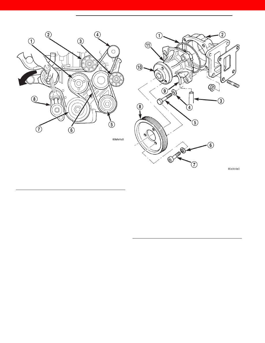
Fig. 21 Automatic Belt Tensioner Assembly

1 – FAN PULLEY
2 – IDLER PULLEY
3 – IDLER PULLEY
4 – GENERATOR
5 – POWER STEERING PUMP
6 – DRIVE BELT
7 – CRANKSHAFT PULLEY
8 – AUTOMATIC BELT TENSIONER

Fig. 22 WATER PUMP REMOVAL/INSTALL—

TYPICAL

1 – O-RING SEAL
2 – WATER PUMP ADAPTER
3 – DRAIN HOSE
4 – WASHER
5 – PUMP MOUNTING BOLTS (4)
6 – WASHER
7 – WATER PUMP PULLEY BOLTS (3)
8 – WATER PUMP PULLEY
9 – VENT TUBE
10 – PUMP HUB
11 – WATER PUMP

7 - 24

COOLING SYSTEM

XJ

REMOVAL AND INSTALLATION (Continued)

2000 JEEP CHEROKEE

(9) A metal coolant tube (used to connect rubber

coolant hoses), and its mounting bracket are attached
to the front of the water pump (Fig. 26). A rubber
hose connects this tube to the engine. Disconnect the
hose clamp and rubber hose at the back of the ther-
mostat. Position the hose to the side.

(10) Remove the 3 water pump pulley bolts (Fig.

22).

Fig. 23 Thermal Viscous Fan Drive and Blade

Assembly

1 – FAN PULLEY
2 – FAN DRIVE-TO-FAN BLADE BOLTS (4)
3 – MOUNTING NUT
4 – THERMAL VISCOUS FAN DRIVE
5 – FAN BLADES
6 – FAN PULLEY SHAFT
7 – WATER PUMP

Fig. 24 Hose Clamp Tool

1 – HOSE CLAMP TOOL 6094
2 – HOSE CLAMP

Fig. 25 Clamp Number/Letter Location

1 – TYPICAL CONSTANT TENSION HOSE CLAMP
2 – CLAMP NUMBER/LETTER LOCATION
3 – TYPICAL HOSE

Fig. 26 Coolant Tube at Water Pump

1 – COOLANT TUBE
2 – WATER PUMP
3 – BRACKET

XJ

COOLING SYSTEM

7 - 25

REMOVAL AND INSTALLATION (Continued)

2000 JEEP CHEROKEE

(11) Remove the water pump pulley from the

water pump.

(12) Disconnect the drain hose from the vent tube

at the bottom of water pump (Fig. 22).

(13) Remove the 4 water pump mounting bolts

(Fig. 22).

(14) Remove water pump from engine.

INSTALLATION

(1) Clean the o-ring mating surfaces. If the origi-

nal pump is to be reinstalled, remove any deposits or
other foreign material. Inspect the water pump,
water pump adapter and water pump mating sur-
faces for erosion or damage from cavitation.

(2) Position a new rubber o-ring seal (Fig. 22)

between the pump and pump adapter. Hold the seal
with petroleum jelly.

(3) Position the pump on the engine.
(4) Position the metal coolant tube and its mount-

ing bracket on the pump.

(5) Install the four water pump mounting bolts.

Torque bolts to 24 N·m (18 ft. lbs.).

(6) Install drain hose to vent tube at bottom of

pump.

(7) Position the water pump pulley to the water

pump.

(8) Install the water pump pulley bolts finger

tight.

(9) Install the rubber coolant hose near the ther-

mostat.

(10) Install the accessory drive belt. For proce-

dures, refer to Belt Removal/Installation in the
Engine Accessory Drive Belt section of this group.

(11) Torque the water pump pulley bolts to 24 N·m

(18 ft. lbs.).

(12) Position the viscous drive/fan blade and fan

shroud to the engine compartment as one assembly.

(13) Install the thermal viscous fan drive and fan

blade to fan pulley. Torque to 56 N·m (41 ft. lbs.).

(14) Install the fan shroud mounting bolts. Torque

bolts to 3 N·m (31 in. lbs.).

(15) Fill the cooling system with coolant and check

for leaks. Refer to Refilling Cooling System in this
group.

(16) Connect the negative battery cable.
(17) Start and warm the engine. Check for leaks.

CLEANING AND INSPECTION

WATER PUMP

INSPECTION

Replace the water pump assembly if it has any of

the following conditions:

• The body is cracked or damaged

• Water leaks from the shaft seal. This is evident

by traces of coolant below the vent tube drain hose

• Loose or rough turning bearing.

• Impeller rubs either the water pump body or

water pump adapter.

RADIATOR CLEANING

The radiator and air conditioning fins should be

cleaned when an accumulation of bugs, leaves etc.
has occurred. Clean radiator fins are necessary for
good heat transfer. With the engine cold, apply cold
water and compressed air to the back (engine side) of
the radiator to flush the radiator and/or A/C con-
denser of debris.

FAN BLADE

INSPECTION

The fan cannot be repaired. If fan is damaged, it

must be replaced. Inspect fan as follows:

(1) Remove fan blade and viscous fan drive as an

assembly from the engine.

(2) Remove fan blade assembly from viscous fan

drive unit (four bolts) (Fig. 27).

(3) Lay fan on a flat surface with leading edge fac-

ing down. With tip of blade touching flat surface,
replace fan if clearance between opposite blade and
surface is greater than 2.0 mm (.090 inch). Rocking
motion of opposite blades should not exceed 2.0 mm
(.090 inch). Test all blades in this manner.

WARNING: DO

NOT

ATTEMPT

TO

BEND

OR

STRAIGHTEN FAN BLADES IF NOT WITHIN SPECI-
FICATIONS.

(4) Inspect fan assembly for cracks, bends, loose

rivets or broken welds. Replace fan if any damage is
found.

CAUTION: If

fan

blade

assembly

is

replaced

because of mechanical damage, the fan pulley bear-
ing and viscous fan drive should also be inspected.
These components could have been damaged due
to excessive vibration.

CAUTION: Some engines equipped with serpentine
drive belts have reverse rotating fans and viscous
fan

drives.

They

are

marked

with

the

word

REVERSE to designate their usage. Installation of
the wrong fan or viscous fan drive can result in
engine overheating.

7 - 26

COOLING SYSTEM

XJ

REMOVAL AND INSTALLATION (Continued)

2000 JEEP CHEROKEE

PRESSURE/VENT CAP

INSPECTION

Visually inspect the gasket on the cap. Replace cap

if the gasket is swollen, torn or worn. Inspect the
area around the coolant tank filler neck for white
deposits that indicate a leaking cap.

The cap must be replaced by a similar threaded-on

unit with the correct operating pressures if replace-
ment is necessary.

COOLING SYSTEM CLEANING/REVERSE
FLUSHING

CAUTION: The cooling system normally operates at
90-to-117 kPa (13- to-17 psi) pressure. Exceeding
this pressure may damage the radiator or hoses.

CLEANING

Drain cooling system and refill with water. Run

engine with coolant tank pressure/vent cap installed
until upper radiator hose is hot. Stop engine and
drain water from system. If water is dirty, fill system
with water, run engine and drain system. Repeat
until water drains clean.

REVERSE FLUSHING

Reverse flushing of the cooling system is the forc-

ing of water through the cooling system. This is done
using air pressure in the opposite direction of normal
coolant flow. It is usually only necessary with very
dirty systems with evidence of partial plugging.

REVERSE FLUSHING RADIATOR

Disconnect the radiator hoses from the radiator fit-

tings. Attach a section of radiator hose to the radia-
tor bottom outlet fitting and insert the flushing gun.
Connect a water supply hose and air supply hose to
the flushing gun.

CAUTION: The cooling system normally operates at
90-to-117 kPa (13- to-17 psi) pressure. Exceeding
this pressure may damage the radiator or hoses.

Allow the coolant tank and radiator to fill with

water. When radiator is filled, apply air in short
blasts allowing radiator to refill between blasts. Con-
tinue this reverse flushing until clean water flows
out through rear of radiator cooling tube passages.
For more information, refer to operating instructions
supplied with flushing equipment. Have radiator
cleaned more extensively by a radiator repair shop.

REVERSE FLUSHING ENGINE

Drain the cooling system. Remove the thermostat

housing and thermostat. Install the thermostat hous-
ing. Disconnect the radiator upper hose from the
radiator and attach the flushing gun to the hose. Dis-
connect the radiator lower hose from the water
pump. Attach a lead away hose to the water pump
inlet fitting.

CAUTION: Be sure that the heater water control
valve is closed (heat off). This is done to prevent
coolant flow with scale and other deposits from
entering the heater core.

Connect the water supply hose and air supply hose

to the flushing gun. Allow the engine to fill with
water. When the engine is filled, apply air in short
blasts, allowing the system to fill between air blasts.
Continue until clean water flows through the lead
away hose. For more information, refer to operating
instructions supplied with flushing equipment.

Fig. 27 Thermal Viscous Fan Drive and Blade

Assembly

1 – FAN PULLEY
2 – FAN DRIVE-TO-FAN BLADE BOLTS (4)
3 – MOUNTING NUT
4 – THERMAL VISCOUS FAN DRIVE
5 – FAN BLADES
6 – FAN PULLEY SHAFT
7 – WATER PUMP

XJ

COOLING SYSTEM

7 - 27

CLEANING AND INSPECTION (Continued)

2000 JEEP CHEROKEE


Content   ..  77  78  79  80   ..