Jeep XJ. Manual - part 68


  Index      Jeep     Jeep XJ - service repair manual 2001 year


Search            


Content   ..  66  67  68  69   ..


Jeep XJ. Manual - part 68


RADIATOR CAP-TO-FILLER NECK SEAL—
PRESSURE RELIEF CHECK

With radiator cap installed on filler neck, remove

coolant reserve/ overflow tank hose from nipple on
filler neck. Connect a hand operated vacuum pump
to nipple. Operate pump until a reading of 47-to-61
kPa (14- to-18 in. Hg) appears on gauge. If the read-
ing stays steady, or drops slightly and then remains
steady, the pressure valve seal is good. Replace radi-
ator cap if reading does not hold.

WARNING: THE WARNING WORDS -DO NOT OPEN
HOT- ON THE RADIATOR PRESSURE CAP (Fig. 19)
ARE A SAFETY PRECAUTION. WHEN HOT, PRES-
SURE BUILDS UP IN COOLING SYSTEM. TO PRE-
VENT SCALDING OR INJURY, THE RADIATOR CAP
SHOULD NOT BE REMOVED WHILE THE SYSTEM
IS HOT AND/OR UNDER PRESSURE.

There is no need to remove the radiator cap

except for the following purposes:

(1) To check and adjust antifreeze freeze point.
(2) To refill system with new antifreeze.
(3) For conducting service procedures.
(4) When checking for vacuum leaks.

WARNING: IF VEHICLE HAS BEEN RUN RECENTLY,
WAIT AT LEAST 15 MINUTES BEFORE REMOVING
RADIATOR CAP. WITH A RAG, SQUEEZE RADIATOR
UPPER HOSE TO CHECK IF SYSTEM IS UNDER
PRESSURE. PLACE A RAG OVER THE CAP AND
WITHOUT

PUSHING

DOWN,

ROTATE

CAP

COUNTER-CLOCKWISE

TO

THE

FIRST

STOP.

ALLOW FLUID TO ESCAPE THROUGH OVERFLOW
HOSE

INTO

COOLANT

RESERVE/OVERFLOW

TANK. SQUEEZE RADIATOR UPPER HOSE TO
DETERMINE

WHEN

PRESSURE

HAS

BEEN

RELEASED. WHEN COOLANT AND STEAM STOP
BEING PUSHED INTO TANK AND SYSTEM PRES-
SURE DROPS, REMOVE RADIATOR CAP COM-
PLETELY.

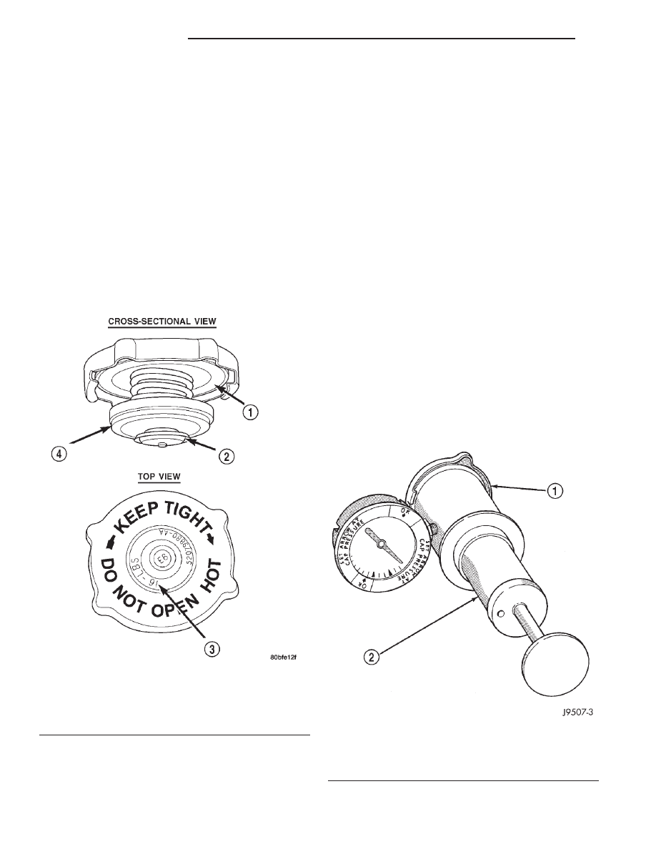
RADIATOR CAP—PRESSURE TESTING

Remove cap from radiator. Be sure that sealing

surfaces are clean. Moisten rubber gasket with water
and install the cap on pressure tester (tool 7700 or
an equivalent) (Fig. 20).

Fig. 19 Radiator Pressure Cap

1 – FILLER NECK SEAL
2 – VACUUM VENT VALVE
3 – PRESSURE RATING
4 – PRESSURE VALVE

Fig. 20 Pressure Testing Radiator Pressure

Cap—Typical

1 – PRESSURE CAP
2 – TYPICAL COOLING SYSTEM PRESSURE TESTER

7 - 20

COOLING SYSTEM

XJ

DIAGNOSIS AND TESTING (Continued)

Operate the tester pump and observe the gauge

pointer at its highest point. The cap release pressure
should be 83-to-110 kPa (12-to-16 psi). The cap is sat-
isfactory when the pressure holds steady. It is also
good if it holds pressure within the 83-to-110 kPa
(12-to-16 psi) range for 30 seconds or more. If the
pointer drops quickly, replace the cap.

CAUTION: Radiator pressure testing tools are very
sensitive to small air leaks, which will not cause
cooling system problems. A pressure cap that does
not have a history of coolant loss should not be
replaced just because it leaks slowly when tested
with this tool. Add water to tool. Turn tool upside
down and recheck pressure cap to confirm that cap
needs replacement.

CAP INSPECTION
Visually inspect the pressure valve gasket on the

cap. Replace cap if the gasket is swollen, torn or
worn. Inspect the area around radiator filler neck for
white deposits that indicate a leaking cap.

COOLANT—LOW LEVEL AERATION

If the coolant level in radiator drops below top of

radiator core tubes, air will enter cooling system.

Low coolant level can cause thermostat pellet to be

suspended in air instead of coolant. This will cause
thermostat to open later, which in turn causes higher
coolant temperature. Air trapped in cooling system
also reduces amount of coolant circulating in heater
core resulting in low heat output.

DEAERATION

As the engine operates, any air trapped in cooling

system gathers under the radiator cap. The next time
the engine is operated, thermal expansion of coolant
will push any trapped air past radiator cap into the
coolant reserve/overflow tank. Here it escapes to the
atmosphere into the tank. When the engine cools
down the coolant, it will be drawn from the reserve/
overflow tank into the radiator to replace any
removed air.

SERVICE PROCEDURES

COOLANT—ROUTINE LEVEL CHECK

NOTE:

Do not remove radiator cap for routine

coolant level inspections. The coolant level can be
checked at coolant reserve/overflow tank.

The coolant reserve/overflow system provides a

quick visual method for determining coolant level
without removing radiator pressure cap. With engine
cold and not running, observe coolant level in
reserve/overflow tank. The coolant level should be
between ADD and FULL marks.

COOLANT—ADDING ADDITIONAL

Do not remove radiator cap to add coolant to

system. When adding coolant to maintain correct
level, do so at coolant reserve/overflow tank. Use a
50/50 mixture of ethylene-glycol antifreeze containing
Alugard 340-2

y and low mineral content water.

Remove radiator cap only for testing or when refill-
ing system after service. Removing cap unnecessarily
can cause loss of coolant and allow air to enter sys-
tem, which produces corrosion.

COOLANT—LEVEL CHECK

The cooling system is closed and designed to main-

tain coolant level to top of radiator.

WARNING: DO NOT OPEN RADIATOR DRAINCOCK
WITH ENGINE RUNNING OR WHILE ENGINE IS HOT
AND COOLING SYSTEM IS UNDER PRESSURE.

When vehicle servicing requires a coolant level

check in radiator, drain several ounces of coolant
from radiator drain cock. Do this while observing
coolant reserve/overflow system tank. The coolant
level in reserve/overflow tank should drop slightly. If
not, inspect for a leak between radiator and coolant
reserve/overflow system connection. Remove radiator
cap. The coolant level should be to top of radiator. If
not and if coolant level in reserve/overflow tank is at
ADD mark, check for:

• An air leak in coolant reserve/overflow tank or

its hose

• An air leak in radiator filler neck

• Leak in pressure cap seal to radiator filler neck

COOLING SYSTEM—DRAINING AND FILLING

DRAINING

WARNING: DO

NOT

REMOVE

THE

CYLINDER

BLOCK DRAIN PLUGS OR LOOSEN THE RADIATOR
DRAINCOCK

WITH

SYSTEM

HOT AND

UNDER

PRESSURE. SERIOUS BURNS FROM COOLANT
CAN OCCUR.

DO NOT WASTE reusable coolant. If the solution

is clean, drain the coolant into a clean container for
reuse.

(1) Remove radiator pressure cap.

XJ

COOLING SYSTEM

7 - 21

DIAGNOSIS AND TESTING (Continued)

(2) For access to radiator draincock (Fig. 21),

remove radiator grille mounting screws and remove
grill. Refer to Group 23, Body for correct procedure.

(3) Attach one end of a 24 inch long X 1/4 inch ID

hose to the radiator draincock. Put the other end into
a clean container. Open draincock and drain coolant
from radiator.

(4) Drain coolant from engine by removing the

drain plug and coolant temperature sensor on left
side of block.

REFILLING

(1) Tighten the radiator petcock and the cylinder

block drain plug(s).

(2) Install grille.
(3) Fill system using a 50/50 mixture of water and

antifreeze as described in the Coolant section of this
group. Fill radiator to top and install radiator cap.
Add sufficient coolant to reserve/overflow tank to
raise level to FULL mark.

(4) With heater control unit in the HEAT position,

operate engine with radiator cap in place.

(5) After engine has reached normal operating

temperature, shut engine off and allow it to cool.

(6) Add coolant to reserve/overflow tank as neces-

sary. Only add coolant when the engine is cold.
Coolant level in a warm engine will be higher
due to thermal expansion.

COOLING SYSTEM—REVERSE FLUSHING

CAUTION: The cooling system normally operates at
97-to-124 kPa (14- to-18 psi) pressure. Exceeding
this pressure may damage the radiator or hoses.

Reverse flushing of the cooling system is the forc-

ing of water through the cooling system. This is done
using air pressure in the opposite direction of normal
coolant flow. It is usually only necessary with very
dirty systems with evidence of partial plugging.

CHEMICAL CLEANING

If visual inspection indicates the formation of

sludge or scaly deposits, use a radiator cleaner
(Mopar Radiator Kleen or equivalent) before flushing.
This will soften scale and other deposits and aid the
flushing operation.

CAUTION: Be sure instructions on the container
are followed.

REVERSE FLUSHING RADIATOR

Disconnect the radiator hoses from the radiator fit-

tings. Attach a section of radiator hose to the radia-
tor bottom outlet fitting and insert the flushing gun.
Connect a water supply hose and air supply hose to
the flushing gun.

CAUTION: The cooling system normally operates at
97-to-124 kPa (14- to-18 psi) pressure. Exceeding
this pressure may damage the radiator or hoses.

Allow the radiator to fill with water. When radiator

is filled, apply air in short blasts allowing radiator to
refill between blasts. Continue this reverse flushing
until clean water flows out through rear of radiator
cooling tube passages. For more information, refer to
operating instructions supplied with flushing equip-
ment. Have radiator cleaned more extensively by a
radiator repair shop.

REVERSE FLUSHING ENGINE

Drain the cooling system. Remove the thermostat

housing and thermostat. Install the thermostat hous-
ing. Disconnect the radiator upper hose from the
radiator and attach the flushing gun to the hose. Dis-
connect the radiator lower hose from the water
pump. Attach a lead away hose to the water pump
inlet fitting.

CAUTION: Be sure that the heater control valve is
closed (heat off). This is done to prevent coolant
flow with scale and other deposits from entering
the heater core.

Connect the water supply hose and air supply hose

to the flushing gun. Allow the engine to fill with
water. When the engine is filled, apply air in short
blasts, allowing the system to fill between air blasts.
Continue until clean water flows through the lead
away hose. For more information, refer to operating
instructions supplied with flushing equipment.

Fig. 21 Radiator Petcock—2.5L/4.0L (LHD/RHD)

1 – RADIATOR PETCOCK

7 - 22

COOLING SYSTEM

XJ

SERVICE PROCEDURES (Continued)

Remove the lead away hose, flushing gun, water

supply hose and air supply hose. Remove the thermo-
stat housing and install thermostat. Install the ther-
mostat housing with a replacement gasket. Refer to
Thermostat

Replacement.

Connect

the

radiator

hoses. Refill the cooling system with the correct anti-
freeze/water mixture.

REMOVAL AND INSTALLATION

TRANSMISSION OIL COOLERS

WATER-TO-OIL COOLER

The internal transmission oil cooler located within

the radiator is not serviceable. If it requires service,
the radiator must be replaced.

Once the repaired or replacement radiator has been

installed, fill the cooling system and inspect for leaks.
Refer to the Refilling Cooling System and Testing
Cooling System For Leaks sections in this group. If
the transmission operates properly after repairing the
leak, drain the transmission and remove the transmis-
sion oil pan. Inspect for sludge and/or rust. Inspect for
a dirty or plugged inlet filter. If none of these condi-
tions are found, the transmission and torque convertor
may not require reconditioning. Refer to Group 21 for
automatic transmission servicing.

AIR-TO-OIL COOLER

REMOVAL

(1) Remove the grill mounting screws and remove

the grill. Refer to Group 23, Body for procedures.

(2) Place a drain pan below the transmission oil

cooler.

(3) Remove the two constant tension clamps at oil

cooler inlet and outlet tubes.

(4) Remove the two oil cooler mounting bolts (Fig.

22).

(5) Remove the oil cooler from vehicle.

INSTALLATION

(1) Position

and

secure

oil

cooler

to

vehicle.

Tighten mounting bolts to 8 N·m (72 in. lbs.) torque.

(2) Secure inlet and outlet tubes with constant

tension clamps.

Install the grill.
(3) Start engine and check transmission fluid level.

Add fluid if necessary.

COOLANT RESERVE TANK

REMOVAL

(1) Remove the tube clamp at the tank and remove

tube.

(2) Remove the tank mounting bolts and remove

tank (Fig. 23) (Fig. 24).

Fig. 22 Auxiliary Air-To-Oil Cooler

1 – AIR CONDITIONING CONDENSER
2 – HOSE CLAMPS (2)
3 – AUXILIARY AUTOMATIC TRANSMISSION OIL COOLER
4 – MOUNTING BOLT
5 – MOUNTING BOLT

Fig. 23 Reserve/Overflow Tank—Except Right Hand

Drive

1 – COOLANT RESERVE/OVERFLOW TANK
2 – CLAMP
3 – MOUNTING BOLTS
4 – TUBE TO RADIATOR

XJ

COOLING SYSTEM

7 - 23

SERVICE PROCEDURES (Continued)


Content   ..  66  67  68  69   ..