Jeep XJ. Manual - part 62


  Index      Jeep     Jeep XJ - service repair manual 2001 year


Search            


Content   ..  60  61  62  63   ..


Jeep XJ. Manual - part 62


INSTALLATION

CAUTION: The bearing can be installed incorrectly
if care is not exercised. Make sure the stamped let-
ters on the bearing will be facing out (toward rear
of vehicle) after installation.

(1) Lightly scuff sand the flywheel surface with

180 grit emery cloth. Clean the surface with Mopar

t

brake or carburetor cleaner.

(2) Install the new pilot bearing with hammer and

tool handle C-4171. (Fig. 9). Seat the bearing flush
with lower edge of chamfer in retainer bore (Fig. 10).
Reposition the bearing if necessary.

(3) Install the bearing retainer. Torque bolts to 28

N·m (20 ft. lbs.)

(4) Lubricate the pilot bearing with Mopar

t high

temperature wheel bearing grease.

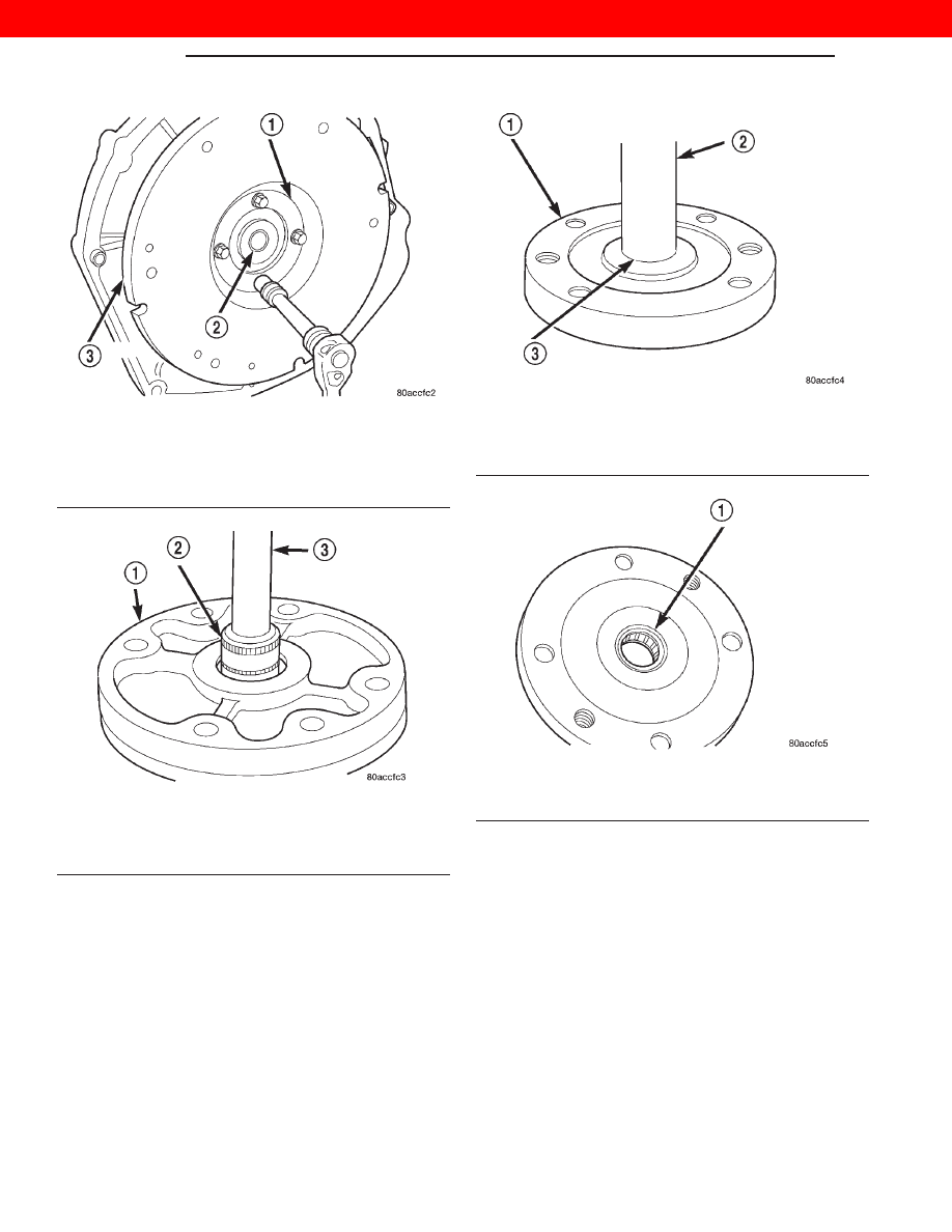
Fig. 7 Pilot Bearing Retainer Bolt Removal/

Installation

1 – RETAINER
2 – PILOT BEARING
3 – FLYWHEEL

Fig. 8 Pilot Bearing Removal

1 – HOUSING
2 – SUITABLE SIZE SOCKET
3 – EXTENSION

Fig. 9 Pilot Bearing Installation

1 – HOUSING
2 – SPECIAL TOOL C-4171
3 – BEARING

Fig. 10 Pilot Bearing Seated In Retainer

1 – SEAT PILOT BEARING FLUSH WITH LOWER EDGE OF

CHAMFER (IN BORE)

6 - 4

CLUTCH

XJ

REMOVAL AND INSTALLATION (Continued)

2000 JEEP CHEROKEE

(5) Install the clutch disc and cover (Fig. 11). Refer

to clutch cover and disc removal and installation in
this group.

(6) Install the transmission and transfer case.

Refer to Group 21, Transmission and Transfer Case
for procedures.

FLYWHEEL

REMOVAL

(1) Remove the transmission and clutch housing.

Refer to Group 21, Transmission and Transfer Case
for procedure.

(2) Remove the clutch cover and disc (Fig. 12) as

described in this section.

(3) Remove the bolts that attach pilot bearing

retainer to flywheel.

(4) Remove the pilot bearing and retainer.
(5) Remove the flywheel bolts.
(6) Grasp the flywheel firmly and work it off the

crankshaft flange.

(7) Remove the o-ring from the crankshaft flange,

or the mounting shoulder of the flywheel (Fig. 14).

(8) Clean the flywheel in solvent.

INSPECTION

Examine the flywheel mounting surfaces, clutch

contact surface, and ring gear. Check condition of fly-
wheel hub and attaching bolts. Replace flywheel if
hub exhibits cracks in the area of attaching bolt
holes. Replace ring gear if the teeth are damaged.
Resurface the flywheel if the clutch contact surface is
scored or rough (refer to flywheel finishing and ring
gear replacement information in this section.

Check flywheel runout if misalignment is sus-

pected. Runout should not exceed 0.08 mm. Measure
flywheel face runout with a dial indicator (Fig. 13).
Mount the indicator on a stud installed in the engine
block or in one of the flywheel attaching bolt holes.
Face runout can be corrected by resurfacing if neces-
sary. Surface grinding equipment is recommended for
this purpose. Stock removal should not exceed 0.25
mm.

INSTALLATION

CAUTION: Use NEW flywheel bolts for the following
procedure.

(1) Clean the crankshaft flange before mounting

the flywheel. Dirt or grease on flange surface may
cock flywheel causing run-out.

Fig. 11 Clutch Cover (Pressure Plate) View

1 – VEHICLE UNDERBODY
2 – ENGINE SPEED SENSOR
3 – PRESSURE PLATE RETAINING BOLTS
4 – CLUTCH COVER (PRESSURE PLATE)
5 – ENGINE OIL PAN
6 – PRESSURE PLATE RETAINING BOLTS

Fig. 12 Clutch Cover (Pressure Plate) View

1 – VEHICLE UNDERBODY
2 – ENGINE SPEED SENSOR
3 – PRESSURE PLATE RETAINING BOLTS
4 – CLUTCH COVER (PRESSURE PLATE)
5 – ENGINE OIL PAN
6 – PRESSURE PLATE RETAINING BOLTS

XJ

CLUTCH

6 - 5

REMOVAL AND INSTALLATION (Continued)

2000 JEEP CHEROKEE

(2) Install new o-ring in the flywheel mounting

flange (Fig. 14). Use grease to hold the ring in place.

(3) Install the flywheel on the crankshaft and

align the bolt holes.

(4) Install and tighten the new flywheel bolts as

follows:

(a) Lubricate and install the 6 new flywheel

bolts.

(b) Torque the 6 flywheel bolts to 49 N

•m (36 ft.

lbs.) starting with one bolt and following with the
opposite one (cross tightening) until completion, in
a clockwise direction (Fig. 15).

(c) Loosen one bolt at a time and tighten to 19.6

N

•m (14 ft. lbs.) plus 75° using the cross tighten-

ing method until completion.

(5) Install the clutch cover and disc (Fig. 16). Refer

to clutch cover and disc removal and installation pro-
cedure in this section.

(6) Install the transmission and transfer case.

Refer to Group 21, Transmission and Transfer Case
for removal and installation procedure.

Fig. 13 Checking Flywheel Runout

1 – DIAL INDICATOR
2 – FLYWHEEL FACE

Fig. 14 Flywheel Mounting (VM Diesel)

1 – O-RING
2 – PILOT BEARING HOUSING
3 – FLYWHEEL
4 – STARTER RING GEAR

Fig. 15 Cross Tightening Method

Fig. 16 Clutch Cover (Pressure Plate) View

1 – VEHICLE UNDERBODY
2 – ENGINE SPEED SENSOR
3 – PRESSURE PLATE RETAINING BOLTS
4 – CLUTCH COVER (PRESSURE PLATE)
5 – ENGINE OIL PAN
6 – PRESSURE PLATE RETAINING BOLTS

6 - 6

CLUTCH

XJ

REMOVAL AND INSTALLATION (Continued)

2000 JEEP CHEROKEE

FLYWHEEL RING GEAR

REMOVAL

(1) Remove the transmission and transfer case.

Refer to Group 21, Transmission and Transfer Case
for removal and installation procedures.

(2) Remove the clutch cover and disc (Fig. 17).

Refer to clutch cover and disc removal and installa-
tion in this group.

(3) Remove the flywheel. Refer to flywheel removal

and installation in this group.

(4) Mark position of the old gear for alignment ref-

erence. Use a carbide tipped scribe to mark gear loca-
tion on flywheel.

(5) Wear protective goggles or approved safety

glasses.

(6) Remove the old gear by cutting most of the way

through it at one point. Use an abrasive cut off wheel
for this purpose. Break the ring gear at cut with a
hammer and a cold chisel or punch

(7) Ring gear is shrink fit on flywheel. This means

the gear must be expanded by heating in order to
install it.

NOTE: The method of heating and expanding the
new ring gear is extremely important. Every surface
of the gear must be heated at the same time to pro-
duce

uniform

expansion.

An

oven

or

similar

enclosed heating device must be used. Temperature
required for uniform expansion is approximately
350°-375°.

CAUTION: Do not use an oxy/acetylene torch to
remove the old gear, or to heat and expand a new
gear. The high temperature of the torch flame can
cause localized heating that will damage the fly-
wheel. In addition, using the torch to heat a replace-
ment

gear

will

cause

uneven

heating

and

expansion. The torch flame can also anneal the
gear teeth resulting in rapid wear and damage after
installation.

INSTALLATION

(1) Position and install the heated ring gear on the

flywheel:

(a) Wear heat resistant gloves to handle the hot

ring gear.

(b) Align the ring gear on the flywheel evenly.
(c) Use hammer and brass drift to tap ring gear

onto the flywheel.

(d) Seat the ring gear on flywheel

(2) Allow the ring gear to cool down before instal-

lation on the engine. Place flywheel on work bench
and let it cool in normal shop air.

(3) Install the flywheel and torque bolts. Refer to

flywheel removal and installation in this group.

(4) Install the clutch cover and disc (Fig. 18). Refer

to clutch cover and disc removal and installation in
this group.

(5) Install the transmission and transfer case.

Refer to Group 21, Transmission and Transfer Case
for removal and installation procedures.

CAUTION: Do not use water or compressed air to
cool the flywheel. The rapid cooling produced by
water or compressed air will distort or crack the
new gear.

Fig. 17 Clutch Cover (Pressure Plate) View

1 – VEHICLE UNDERBODY
2 – ENGINE SPEED SENSOR
3 – PRESSURE PLATE RETAINING BOLTS
4 – CLUTCH COVER (PRESSURE PLATE)
5 – ENGINE OIL PAN
6 – PRESSURE PLATE RETAINING BOLTS

XJ

CLUTCH

6 - 7

REMOVAL AND INSTALLATION (Continued)

2000 JEEP CHEROKEE


Content   ..  60  61  62  63   ..