Jeep XJ. Manual - part 50


  Index      Jeep     Jeep XJ - service repair manual 2001 year


Search            


Content   ..  48  49  50  51   ..


Jeep XJ. Manual - part 50


INSTALLATION

(1) Install pedal and support bracket as an assem-

bly into the vehicle.

(2) Install nuts securing the booster to the pedal

support bracket and nuts to the column bracket.

(3) Tighten nuts to 39 N·m (29 ft. lbs.).
(4) Lubricate the brake pedal pin and bushings

with Mopar multi-mileage grease.

(5) Install booster push rod on pedal pin and

install new retainer clip.

(6) Install knee blocker.

COMBINATION VALVE

NOTE: The combination valve is not repairable. The
valve is serviced as an assembly only.

REMOVAL

(1) Remove air cleaner cover and hose for access to

valve.

(2) Unsnap connector lock tabs and disconnect dif-

ferential pressure switch wire at combination valve
(Fig. 19). Do not pull switch wire to disconnect.

(3) Disconnect brake lines at combination valve

(Fig. 20).

(4) Remove mounting nut and remove valve.

INSTALLATION

(1) Install valve and tighten mounting nut to 17

N·m (155 in. lbs.).

(2) Connect brake lines to replacement valve. Start

line fittings by hand to avoid cross threading.

(3) Tighten brake line fittings to 14 N·m (124 in.

lbs.).

(4) Connect wire to pressure differential switch.
(5) Bleed base brakes.

MASTER CYLINDER

REMOVAL

(1) Remove brake lines at master cylinder and

combination valve (Fig. 20).

(2) Disconnect differential pressure switch wire

from the combination valve.

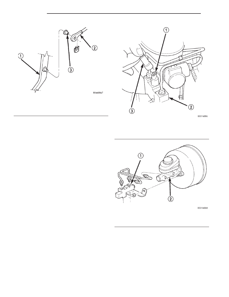
Fig. 18 Booster Push Rod

1 – BRAKE PEDAL
2 – BOOSTER ROD
3 – BUSHING

Fig. 19 Differential Pressure Switch

1 – SWITCH TERMINAL
2 – COMBINATION VALVE
3 – WIRE HARNESS CONNECTOR

Fig. 20 Combination Valve

1 – COMBINATION VALVE
2 – MASTER CYLINDER

5 - 16

BRAKES

XJ

REMOVAL AND INSTALLATION (Continued)

(3) Remove mounting nuts from the combination

valve bracket and remove the valve (Fig. 20).

(4) Remove mounting nuts from the master cylin-

der (Fig. 21).

(5) Remove master cylinder.
(6) Remove cylinder cover and drain fluid.
(7) If master cylinder reservoir requires service,

refer to reservoir replacement procedure in this sec-
tion.

INSTALLATION

NOTE: If master cylinder is replaced, bleed cylinder
before installation.

(1) Remove protective sleeve from primary piston

shank on new master cylinder.

(2) Clean cylinder mounting surface of brake

booster.

(3) Install master cylinder onto brake booster

studs.

(4) Install mounting nuts and tighten to 17 N·m

(155 in. lbs.).

(5) Install combination valve and install mounting

nuts.

(6) Connect brake lines to master cylinder and

combination valve and tighten to 14 N·m (124 in.
lbs.).

(7) Connect differential pressure switch wire to the

combination valve.

(8) On RHD vehicles install the coolant reserve/

overflow tank. Refer to Group 7 Cooling System.

(9) Fill and bleed base brake system.

POWER BRAKE BOOSTER

REMOVAL

(1) On RHD vehicles remove the coolant reserve/

overflow tank. Refer to Group 7 Cooling System.

(2) Disconnect brake lines at master cylinder.
(3) Disconnect wire at combination valve differen-

tial pressure switch.

(4) Remove

nut

mounting

combination

valve

bracket to booster studs and remove valve.

(5) Remove nuts mounting master cylinder to

booster studs and remove cylinder.

(6) Disconnect vacuum hose from booster check

valve.

(7) Remove knee blocker under the steering col-

umn.

(8) Remove retaining clip that secures booster

push rod to brake pedal (Fig. 22).

(9) Remove nuts attaching booster to passenger

compartment side of dash panel (Fig. 23).

(10) In engine compartment, slide booster studs

out of dash panel, tilt booster upward, and remove
booster from engine compartment.

(11) Remove dash seal from booster.

INSTALLATION

(1) Install dash seal on booster.
(2) Align and position booster on dash panel.
(3) In

passenger

compartment,

install

booster

mounting nuts. Tighten nuts just enough to hold
booster in place.

(4) Slide booster push rod onto the brake pedal.

Then secure push rod to pedal pin with retaining
clip.

Fig. 21 Master Cylinder

1 – BOOSTER
2 – MASTER CYLINDER

Fig. 22 Booster Push Rod

1 – BRAKE PEDAL
2 – BOOSTER ROD
3 – BUSHING

XJ

BRAKES

5 - 17

REMOVAL AND INSTALLATION (Continued)

NOTE: Lubricate the pedal pin and bushing with
Mopar multi-mileage grease before installation.

(5) Tighten booster mounting nuts to 39 N·m (29

ft. lbs.).

(6) Install the knee blocker.
(7) If original master cylinder is being installed,

check condition of seal at rear of master cylinder.
Replace seal if cut, or torn.

(8) Clean cylinder mounting surface of brake

booster. Use shop towel wetted with brake cleaner for
this purpose. Dirt, grease, or similar materials will
prevent proper cylinder seating and could result in
vacuum leak.

(9) Align and install master cylinder on booster

studs. Install mounting nuts and tighten to 17.5 N·m
(155 in. lbs.).

(10) Connect vacuum hose to booster check valve.
(11) Connect and secure brake lines to combination

valve and master cylinder. Start all brake line fit-
tings by hand to avoid cross threading.

(12) Install combination valve on booster studs.

Tighten bracket mounting nuts to 17.5 N·m (155 in.
lbs.).

(13) Connect wire to combination valve switch.
(14) On RHD vehicles install the coolant reserve/

overflow tank. Refer to Group 7 Cooling System.

(15) Fill and bleed base brake system.
(16) Verify proper brake operation before moving

vehicle.

FRONT DISC BRAKE CALIPER

REMOVAL

(1) Raise and support vehicle.
(2) Remove front wheel and tire assembly.

(3) Drain small amount of fluid from master cylin-

der brake reservoir with suction gun.

(4) Bottom caliper piston in bore with C-clamp.

Position clamp screw on outboard brake shoe and
clamp frame on rear of caliper (Fig. 24). Do not
allow clamp screw to bear directly on outboard
shoe retainer spring. Use wood or metal spacer
between shoe and clamp screw.

(5) Remove brake hose mounting bolt and discard

washers (Fig. 25).

(6) Remove caliper mounting bolts (Fig. 26).

Fig. 23 Booster Mounting

1 – BOOSTER

Fig. 24 Bottoming Caliper Piston With C-Clamp

1 – CALIPER BOSS
2 – OUTBOARD BRAKESHOE
3 – C-CLAMP

Fig. 25 Brake Hose And Bolt

1 – FITTING WASHERS
2 – CALIPERS

5 - 18

BRAKES

XJ

REMOVAL AND INSTALLATION (Continued)

(7) Tilt top of caliper outward with pry tool if nec-

essary (Fig. 27) and remove caliper.

(8) Remove caliper from vehicle.

INSTALLATION

(1) Clean brake shoe mounting ledges with wire

brush and apply light coat of Mopar multi-mileage
grease to surfaces (Fig. 28).

(2) Install caliper by position notches at lower end

of brake shoes on bottom mounting ledge. Then
rotate caliper over rotor and seat notches at upper
end of shoes on top mounting ledge (Fig. 29).

(3) Coat

caliper

mounting

bolts

with

silicone

grease. Then install and tighten bolts to 15 N·m (11
ft. lbs.).

CAUTION: If new caliper bolts are being installed,
or if the original reason for repair was a drag/pull

condition, check caliper bolt length before proceed-
ing. Bolts must not have a shank length greater
than 67.6 mm (2.66 in.) (Fig. 30).

(4) Install brake hose to caliper with new seal

washers and tighten fitting bolt to 31 N·m (23 ft.
lbs.).

Fig. 26 Caliper Mounting Bolts

1 – CALIPER MOUNTING BOLT (2)
2 – CALIPER

Fig. 27 Caliper Removal

1 – TILT CALIPER OUTBOARD TO REMOVE

Fig. 28 Caliper Lubrication Points

1 – BUSHINGS
2 – CALIPER MOUNTING BOLTS
3 – MOUNTING LEDGES

Fig. 29 Caliper Installation

1 – TOP LEDGE
2 – BRAKESHOE TAB ON LEDGE OUTER SURFACE
3 – LEDGE SEATED IN BRAKESHOE NOTCH
4 – BOTTOM LEDGE

XJ

BRAKES

5 - 19

REMOVAL AND INSTALLATION (Continued)


Content   ..  48  49  50  51   ..