Jeep XJ. Manual - part 15


  Index      Jeep     Jeep XJ - service repair manual 2001 year


Search            


Content   ..  13  14  15  16   ..


Jeep XJ. Manual - part 15


(4) Set the yoke in an arbor press or vise with a

socket whose inside diameter is large enough to
receive the bearing cap positioned beneath the yoke.

(5) Position the yoke with the grease fitting, if

equipped, pointing up.

(6) Place

a

socket

with

an

outside

diameter

smaller than the upper bearing cap on the upper
bearing cap and press the cap through the yoke to
release the lower bearing cap (Fig. 19).

(7) If the bearing cap will not pull out of the yoke

by hand after pressing, tap the yoke ear near the
bearing cap to dislodge the cap.

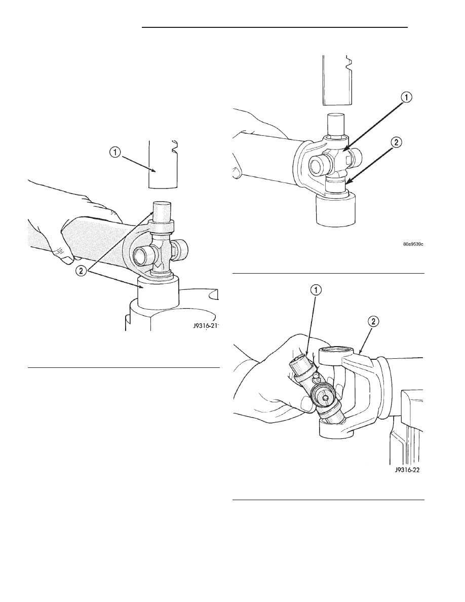
(8) To remove the opposite bearing cap, turn the

yoke over and straighten the cross in the open hole.
Then, carefully press the end of the cross until the
remaining bearing cap can be removed (Fig. 20).

CAUTION: If the cross or bearing cap are not
straight during installation, the bearing cap will
score the walls of the yoke bore and damage can
occur.

ASSEMBLY

(1) Apply extreme pressure (EP) N.L.G.I. Grade 1

or 2 grease to inside of yoke bores to aid in installa-
tion.

(2) Position the cross in the yoke with its lube fit-

ting, if equipped, pointing up (Fig. 21).

(3) Place a bearing cap over the trunnion and

align the cap with the yoke bore (Fig. 22). Keep the
needle bearings upright in the bearing assembly. A
needle bearing lying at the bottom of the cap will
prevent proper assembly.

Fig. 19 Press Out Bearing

1 – PRESS
2 – SOCKET

Fig. 20 Press Out Remaining Bearing

1 – CROSS
2 – BEARING CAP

Fig. 21 Install Cross In Yoke

1 – CROSS
2 – YOKE

3 - 10

PROPELLER SHAFTS

XJ

DISASSEMBLY AND ASSEMBLY (Continued)

(4) Press the bearing cap into the yoke bore

enough to install a snap ring.

(5) Install a snap ring.
(6) Repeat Step 3 and Step 4to install the opposite

bearing cap. If the joint is stiff or binding, strike the
yoke with a soft hammer to seat the needle bearings.

(7) Add grease to lube fitting, if equipped.
(8) Install the propeller shaft.

DOUBLE CARDAN JOINT

DISASSEMBLY

Individual components of cardan universal joints

are not serviceable. If worn or leaking, they must be
replaced as an assembly.

(1) Remove the propeller shaft.
(2) Using a soft drift, tap the outside of the bear-

ing cap assembly to loosen snap ring.

(3) Remove all the bearing cap snap rings (Fig. 23).
(4) Set the joint in an arbor press or vise with a

socket whose inside diameter is large enough to
receive the bearing cap positioned beneath the link
yoke.

(5) Place

a

socket

with

an

outside

diameter

smaller than the upper bearing cap on the upper
bearing cap and partially press one bearing cap from
the outboard side of the link yoke enough to grasp
the bearing cap with vise jaws (Fig. 24). Be sure to
remove grease fittings that interfere with removal.

(6) Grasp the protruding bearing by vise jaws. Tap

the link yoke with a mallet and drift to dislodge the
bearing cap from the yoke (Fig. 25).

(7) Flip assembly and repeat Step 4, Step 5, and

Step 6 to remove the opposite bearing cap. This will
then allow removal of the cross centering kit assem-
bly and spring (Fig. 26).

(8) Press the remaining bearing caps out the other

end of the link yoke as described above to complete
the disassembly.

Fig. 22 Install Bearing On Trunnion

1 – BEARING CAP
2 – TRUNNION

Fig. 23 Remove Snap Rings

Fig. 24 Press Out Bearing

XJ

PROPELLER SHAFTS

3 - 11

DISASSEMBLY AND ASSEMBLY (Continued)

ASSEMBLY

During assembly, ensure that the alignment

marks on the link yoke and propeller shaft
yoke are aligned.

(1) Apply extreme pressure (EP) N.L.G.I. Grade 1

or 2 grease to inside of yoke bores to aid in installa-
tion.

(2) Fit a cross into the propeller shaft yoke (Fig. 27).

(3) Place a bearing cap over the trunnion and

align the cap with the yoke bore (Fig. 28). Keep the
needle bearings upright in the bearing assembly. A
needle bearing lying at the bottom of the cap will
prevent proper assembly.

(4) Press the bearing cap into the yoke bore

enough to install a snap ring (Fig. 29).

(5) Install a snap ring.

Fig. 25 Remove Bearing From Yoke

Fig. 26 Remove Centering Kit

Fig. 27 Install Cross In Yoke

Fig. 28 Install Bearing Cap

3 - 12

PROPELLER SHAFTS

XJ

DISASSEMBLY AND ASSEMBLY (Continued)

(6) Flip the propeller shaft yoke and install the

bearing cap onto the opposite trunnion. Install a
snap ring (Fig. 30).

(7) Fit the link yoke on the remaining two trun-

nions and press both bearing caps into place (Fig.
31).

(8) Install snap rings.

(9) Install the centering kit assembly inside the

link yoke making sure the spring is properly posi-
tioned (Fig. 32).

Fig. 29 Press In Bearing Cap

Fig. 30 Press In Bearing Cap

Fig. 31 Install Link Yoke

Fig. 32 Install Centering Kit

XJ

PROPELLER SHAFTS

3 - 13

DISASSEMBLY AND ASSEMBLY (Continued)


Content   ..  13  14  15  16   ..