Jeep Wrangler TJ. Manual - part 604


  Index      Jeep     Jeep Wrangler TJ - service repair manual 2005 year


Search            


Content   ..  602  603  604  605   ..


Jeep Wrangler TJ. Manual - part 604


It will not be necessary to check the oil level in the

A/C compressor or to add oil, unless there has been
an oil loss. An oil loss may occur due to a rupture or
leak from a refrigerant line, a connector fitting, a
component, or a component seal. If a leak occurs, add
30 milliliters (1 fluid ounce) of refrigerant oil to the
refrigerant system after the repair has been made.
Refrigerant oil loss will be evident at the leak point
by the presence of a wet, shiny surface around the
leak.

Refrigerant oil must be added when an accumula-

tor, A/C evaporator or A/C condenser is replaced. See
the Refrigerant Oil Capacities chart. When an A/C
compressor is replaced, the refrigerant oil must be
drained from the old compressor and measured.
Drain all of the refrigerant oil from the new A/C com-
pressor, then fill the new compressor with the same
amount of refrigerant oil that was drained out of the
old compressor.

REFRIGERANT OIL CAPACITIES

Component

ml

oz

Total System Fill

180

6.1

Accumulator

90

3.0

A/C Condenser

22

0.75

A/C Evaporator

45

1.5

A/C Compressor

Drain and measure the
oil from the old
compressor - see text.

SERVICE PORT VALVE CORE

DESCRIPTION

The A/C service port valve cores are serviceable

items. The high side valve is located on the located
on the manifold directly over the discharge port of
the A/C compressor. The low side valve is located on
the liquid line near the evaporator inlet tube at the
rear of the engine compartment.

Refrigerant system service ports are used to

recover, recycle, evacuate, charge and test the A/C
refrigerant system. Unique sizes are used on the two
service ports for the R-134a refrigerant system to
ensure the system is not accidentally contaminated
with R-12 refrigerant or by service equipment used
for R-12 refrigerant.

The high-side service port is located on the A/C dis-

charge. The low-side service port is located on the
A/C liquid line. Both the high-side and low-side A/C
service port valve cores are serviceable.

NOTE: The protective cap aids in service port seal-
ing and helps protects the refrigerant system from

contamination. Remember to always reinstall the
protective cap onto the service port when refriger-
ant system service is complete.

Each of the service ports has a threaded plastic

protective cap installed over it from the factory. The
service port caps are serviceable items.

REMOVAL

WARNING: Refer to the applicable warnings and
cautions for this system before performing the fol-
lowing operation (Refer to 24 - HEATING & AIR
CONDITIONING/PLUMBING - WARNINGS) and (Refer
to 24 - HEATING & AIR CONDITIONING/PLUMBING -
CAUTIONS). Failure to follow the warnings and cau-
tions could result in possible personal injury or
death.

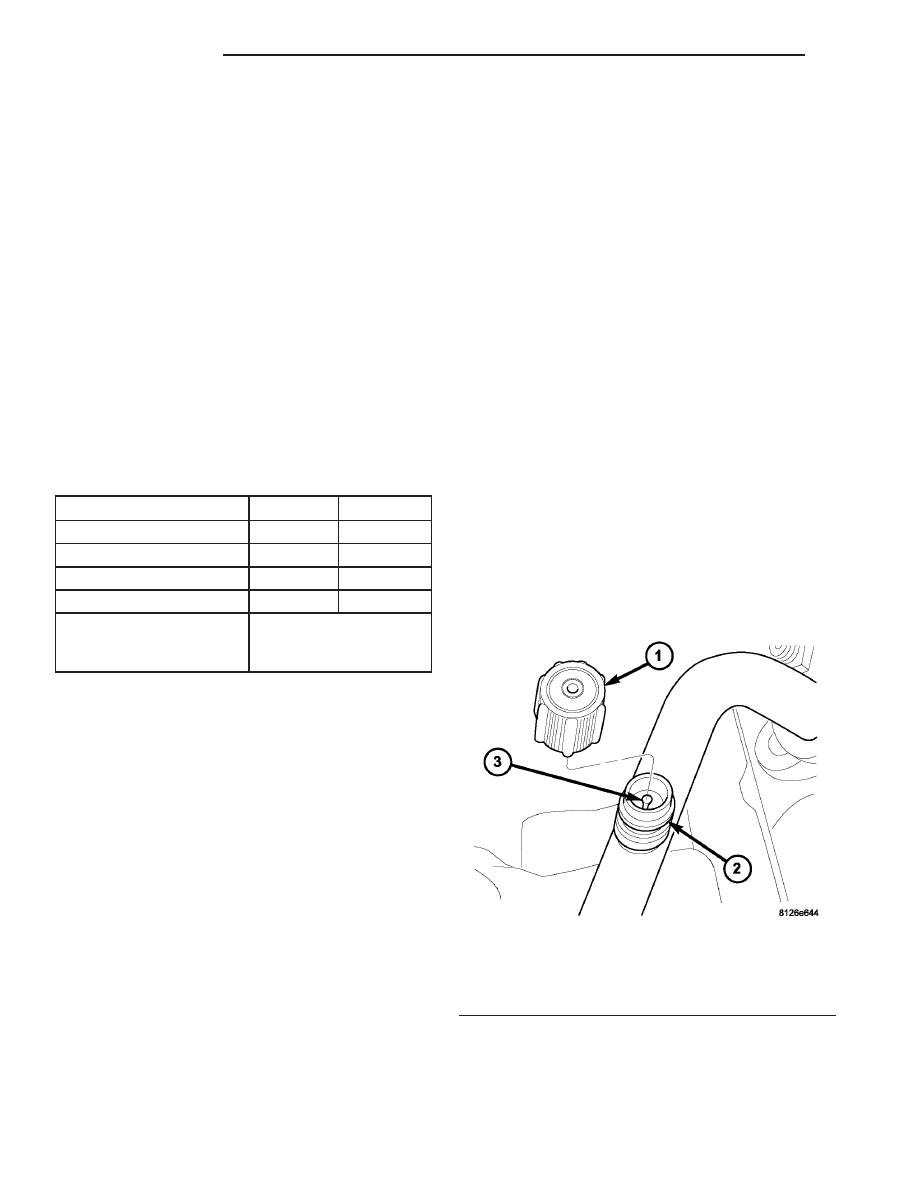
(1) Remove the protective cap from the service port

(Fig. 23).

(2) Recover the refrigerant from the refrigerant

system (Refer to 24 - HEATING & AIR CONDITION-
ING/PLUMBING

-

STANDARD

PROCEDURE

-

REFRIGERANT SYSTEM RECOVERY).

(3) Using a Schrader-type valve core tool, remove

the valve core from the service port.

(4) Install a plug in or tape over the opened ser-

vice port(s).

INSTALLATION

(1) Lubricate the valve core with clean refrigerant

oil prior to installation. Use only refrigerant oil of the
type recommended for the A/C compressor in the
vehicle.

Fig. 23 A/C Service Port-Typical

1 - PROTECTIVE CAP
2 - SERVICE PORT
3 - VALVE CORE

24 - 82

PLUMBING

TJ

REFRIGERANT OIL (Continued)

(2) Remove the tape or plug from the service port.

CAUTION: A valve core that is not fully seated in
the A/C service port can result in damage to the
valve during refrigerant system evacuation and
charge. Such damage may result in a loss of sys-
tem refrigerant while uncoupling the charge adapt-
ers.

(3) Using a Schrader-type valve core tool, install

and tighten the valve core into the service port(s).

(4) Evacuate the refrigerant system (Refer to 24 -

HEATING & AIR CONDITIONING/PLUMBING -
STANDARD PROCEDURE - REFRIGERANT SYS-
TEM EVACUATE).

(5) Charge the refrigerant system (Refer to 24 -

HEATING & AIR CONDITIONING/PLUMBING -
STANDARD PROCEDURE - REFRIGERANT SYS-
TEM CHARGE).

NOTE: The protective cap helps aid in service port
sealing and helps protects the refrigerant system
from contamination. Remember to always reinstall
the protective cap onto the service port when refrig-
erant system service is complete.

(6) Install the protective cap onto the service port.

SUCTION LINE

DESCRIPTION

The A/C suction line is the refrigerant line that

goes from the A/C evaporator to the A/C accumulator,
then to the A/C compressor. The A/C suction line is
serviced in two sections.

CAUTION: Use only O-ring seals specified for the
vehicle. Failure to use the correct O-ring seal will
cause the refrigerant system connections to leak.

The A/C suction lines have no serviceable parts

except for the rubber O-ring seals.

If an A/C suction line is found to be leaking or is

damaged, it must be replaced.

REMOVAL

WARNING: Refer to the applicable warnings and
cautions for this system before performing the fol-
lowing operation (Refer to 24 - HEATING & AIR
CONDITIONING/PLUMBING - WARNINGS) and (Refer
to 24 - HEATING & AIR CONDITIONING/PLUMBING -
CAUTIONS). Failure to follow the warnings and cau-
tions could result in possible personal injury or
death.

(1) Disconnect and isolate the negative battery

cable.

(2) Recover the refrigerant from the refrigerant

system (Refer to 24 - HEATING & AIR CONDITION-
ING/PLUMBING

-

STANDARD

PROCEDURE

-

REFRIGERANT SYSTEM RECOVERY).

(3) Remove the suction line from the retaining clip

located near the accumulator.

(4) Remove the secondary retaining clip from the

spring-lock coupler that secures the suction line to
the A/C evaporator

(5) Using the proper A/C line disconnect tool, dis-

connect the suction line from the A/C evaporator and
remove and discard the O-ring seal (Fig. 24) (Refer to
24 - HEATING & AIR CONDITIONING/PLUMBING/
REFRIGERANT LINE COUPLER - REMOVAL).

(6) Install plugs in, or tape over the opened suc-

tion line fitting and the evaporator port.

(7) Remove the nuts that secure the suction lines

to the accumulator and to the A/C compressor.

(8) Disconnect the suction lines from the accumu-

lator and the A/C compressor.

(9) Install plugs in, or tape over the opened suc-

tion line fittings and the accumulator and compressor
ports.

(10) Remove the suction lines from the vehicle.

Fig. 24 Suction Lines - 4.0L LHD shown, 2.4L and

RHD similar

1 - SUCTION LINE (EVAPORATOR SIDE)
2 - SUPPORT BRACKET
3 - BOLT
4 - RETAINING BAND
5 - ACCUMULATOR
6 - SUCTION LINE (COMPRESSOR SIDE)

TJ

PLUMBING

24 - 83

SERVICE PORT VALVE CORE (Continued)

INSTALLATION

NOTE: Replacement of the refrigerant line O-ring
seals is required anytime a refrigerant line is
opened. Failure to replace the rubber O-ring seals
could result in a refrigerant system leak.

(1) Position the A/C suction line into the engine

compartment, as required.

(2) Remove the tape or plugs from the opened suc-

tion line fittings and the A/C accumulator, A/C com-
pressor and A/C evaporator as required.

(3) Lubricate new rubber O-ring seals with clean

refrigerant oil and install them on the suction line
fittings. Use only the specified O-ring seals as they
are made of a special material for the R-134a system.
Use only refrigerant oil of the type recommended for
the A/C compressor in the vehicle.

(4) Connect the suction lines onto the A/C accumu-

lator and A/C compressor, as required.

(5) Install the nuts that secure the suction lines to

the accumulator. Tighten the nuts to 9 N·m (80 in.
lbs.).

(6) Install the nut that secures the suction line to

the A/C compressor. Tighten the nut to 25 N·m (18 ft.
lbs.).

(7) Connect the suction line spring-lock coupler to

the A/C evaporator (Refer to 24 - HEATING & AIR
CONDITIONING/PLUMBING/REFRIGERANT LINE
COUPLER - INSTALLATION).

(8) Install the secondary retaining clip onto the

spring-lock coupler that secures the suction line to
the A/C evaporator.

(9) Install the suction line into the retaining clip

located near the accumulator.

(10) Reconnect the negative battery cable.
(11) Evacuate the refrigerant system (Refer to 24 -

HEATING & AIR CONDITIONING/PLUMBING -
STANDARD PROCEDURE - REFRIGERANT SYS-
TEM EVACUATE).

(12) Charge the refrigerant system (Refer to 24 -

HEATING & AIR CONDITIONING/PLUMBING -
STANDARD PROCEDURE - REFRIGERANT SYS-
TEM CHARGE).

24 - 84

PLUMBING

TJ

SUCTION LINE (Continued)

EMISSIONS CONTROL

TABLE OF CONTENTS

page

page

EMISSIONS CONTROL

DESCRIPTION

DESCRIPTION - EMISSION CONTROL

SYSTEM . . . . . . . . . . . . . . . . . . . . . . . . . . . . . 1

DESCRIPTION - STATE DISPLAY TEST

MODE . . . . . . . . . . . . . . . . . . . . . . . . . . . . . . . 2

DESCRIPTION - CIRCUIT ACTUATION TEST

MODE . . . . . . . . . . . . . . . . . . . . . . . . . . . . . . . 2

DESCRIPTION - DIAGNOSTIC TROUBLE

CODES . . . . . . . . . . . . . . . . . . . . . . . . . . . . . . 2

DESCRIPTION - TASK MANAGER

. . . . . . . . . . 2

DESCRIPTION - MONITORED SYSTEMS

. . . . 2

DESCRIPTION - TRIP DEFINITION

. . . . . . . . . 4

DESCRIPTION - COMPONENT MONITORS

. . 5

DESCRIPTION - NON-MONITORED

CIRCUITS . . . . . . . . . . . . . . . . . . . . . . . . . . . . 5

DESCRIPTION - HIGH AND LOW LIMITS

. . . . 6

DESCRIPTION - LOAD VALUE

. . . . . . . . . . . . 6

OPERATION - TASK MANAGER

. . . . . . . . . . . . . 6

EVAPORATIVE EMISSIONS

. . . . . . . . . . . . . . . . 10

EMISSIONS CONTROL

DESCRIPTION

DESCRIPTION - EMISSION CONTROL SYSTEM

The Powertrain Control Module (PCM) monitors

many different circuits in the fuel injection, ignition,
emission and engine systems. If the PCM senses a
problem with a monitored circuit often enough to
indicate an actual problem, it stores a Diagnostic
Trouble Code (DTC) in the PCM’s memory. If the
code applies to a non-emissions related component or
system, and the problem is repaired or ceases to
exist, the PCM cancels the code after 40 warm-up
cycles. Diagnostic trouble codes that affect vehicle
emissions illuminate the Malfunction Indicator Lamp
(MIL). The MIL is displayed as an engine icon on the
instrument panel. Refer to Malfunction Indicator
Lamp (MIL) in this section.

Certain criteria must be met before the PCM

stores a DTC in memory. The criteria may be a spe-
cific range of engine RPM, engine temperature,
and/or input voltage to the PCM.

The PCM might not store a DTC for a monitored

circuit even though a malfunction has occurred. This
may happen because one of the DTC criteria for the
circuit has not been met. For example , assume the
diagnostic trouble code criteria requires the PCM to
monitor the circuit only when the engine operates
between 750 and 2000 RPM. Suppose the sensor’s
output circuit shorts to ground when engine operates
above 2400 RPM (resulting in 0 volt input to the
PCM). Because the condition happens at an engine
speed above the maximum threshold (2000 rpm), the
PCM will not store a DTC.

There are several operating conditions for which

the PCM monitors and sets DTC’s. Refer to Moni-
tored Systems, Components, and Non-Monitored Cir-
cuits in this section.

Technicians must retrieve stored DTC’s by connect-

ing the DRB scan tool (or an equivalent scan tool) to
the 16–way data link connector (Fig. 1).

NOTE: Various diagnostic procedures may actually
cause a diagnostic monitor to set a DTC. For
instance, pulling a spark plug wire to perform a
spark test may set the misfire code. When a repair
is completed and verified, connect the DRB scan
tool to the 16–way data link connector to erase all
DTC’s and extinguish the MIL.

Fig. 1 DATA LINK (DIAGNOSTIC) CONNECTOR

LOCATION

1 - 16–WAY DATA LINK CONNECTOR

TJ

EMISSIONS CONTROL

25 - 1


Content   ..  602  603  604  605   ..