Jeep Wrangler TJ. Manual - part 602


  Index      Jeep     Jeep Wrangler TJ - service repair manual 2005 year


Search            


Content   ..  600  601  602  603   ..


Jeep Wrangler TJ. Manual - part 602


and helps to reduce the potential for blockage of the
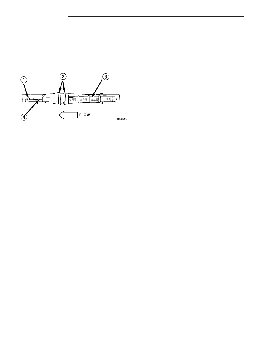
metering orifice by refrigerant system contaminants
(Fig. 14). The outlet end of the tube has a nylon
mesh diffuser screen. The O-rings on the plastic body
of the tube seal it to the inside of the liquid line and
prevent the refrigerant from bypassing the fixed
metering orifice.

OPERATION

The fixed A/C orifice tube is used to meter the flow

of liquid refrigerant into the A/C evaporator. The
high-pressure liquid refrigerant from the A/C con-
denser expands into a low-pressure liquid as it
passes through the metering orifice and diffuser
screen of the A/C orifice tube.

The A/C orifice tube is not serviceable. It cannot be

repaired, and if faulty or plugged, it must be replaced
as part of the A/C liquid line (Refer to 24 - HEATING
& AIR CONDITIONING/PLUMBING/LIQUID LINE
- REMOVAL).

DIAGNOSIS AND TESTING

A/C ORIFICE TUBE

WARNING: The A/C liquid line between the A/C con-
denser and the A/C orifice tube can become hot
enough to burn the skin. Use extreme caution when
performing the following test to prevent possible
personal injury.

NOTE: The A/C orifice tube can be checked for
proper operation using the following procedure.
However, the A/C orifice tube is only serviced as a
part of the A/C liquid line. If the results of this test
indicate that the A/C orifice tube is obstructed or
missing, the A/C liquid line must be replaced.

(1) Confirm that the refrigerant system is properly

charged (Refer to 24 - HEATING & AIR CONDI-

TIONING - DIAGNOSIS AND TESTING - A/C PER-
FORMANCE TEST).

(2) Start the engine. Turn on the A/C system and

confirm that the compressor clutch is engaged.

(3) Allow the A/C system to operate for five min-

utes.

(4) Lightly and cautiously touch the A/C liquid line

near the condenser outlet at the front of the engine
compartment. The liquid line should be hot to the
touch.

(5) Touch the A/C liquid line near the evaporator

inlet at the rear of the engine compartment. The liq-
uid line should be cold to the touch.

(6) If there is a distinct temperature differential

between the two ends of the A/C liquid line, the A/C
orifice tube is in good condition. If there is little or no
detectable temperature differential between the two
ends of the A/C liquid line, the A/C orifice tube is
obstructed or missing and the A/C liquid line must be
replaced (Refer to 24 - HEATING & AIR CONDI-
TIONING/PLUMBING/A/C

LIQUID

LINE

-

REMOVAL).

ACCUMULATOR

DESCRIPTION

The A/C accumulator (Fig. 15) is mounted in the

engine compartment between the A/C evaporator and
the A/C compressor. An integral mounting bracket is
used to secure the A/C accumulator to the frame rail.
The A/C low pressure switch is mounted on a fitting
located on the top of the A/C accumulator.

The A/C accumulator cannot be repaired and, if

faulty or damaged, it must be replaced. The rubber
O-rings used on accumulator connections and the A/C
low pressure switch are available for service replace-
ment.

OPERATION

Refrigerant enters the A/C accumulator mostly as a

low pressure vapor through the inlet tube. Any liq-
uid, oil-laden refrigerant falls to the bottom of the
canister, which acts as a separator. A desiccant bag is
mounted inside the accumulator canister to absorb
any moisture which may have entered and become
trapped within the refrigerant system A filter is also
mounted inside the canister to trap any foreign mate-
rial that may have entered the refrigerant system
during assembly. The low pressure vapor exits the
A/C accumulator through the outlet tube.

The A/C accumulator cannot be repaired. If the A/C

accumulator is faulty or damaged, or if the refriger-
ant system has been contaminated or left open to the
atmosphere for an indeterminable period or if the
A/C compressor has failed, it must be replaced.

Fig. 14 Fixed A/C Orifice Tube - Typical

1 - DIFFUSER SCREEN
2 - O-RING SEALS
3 - INLET FILTER SCREEN
4 - ORIFICE

24 - 74

PLUMBING

TJ

A/C ORIFICE TUBE (Continued)

REMOVAL

WARNING: Refer to the applicable warnings and
cautions for this system before performing the fol-
lowing operation (Refer to 24 - HEATING & AIR
CONDITIONING/PLUMBING - WARNINGS) and (Refer
to 24 - HEATING & AIR CONDITIONING/PLUMBING -
CAUTIONS). Failure to follow the warnings and cau-
tions could result in possible personal injury or
death.

(1) Disconnect and isolate the negative battery

cable.

(2) Recover the refrigerant from the refrigerant

system (Refer to 24 - HEATING & AIR CONDITION-
ING/PLUMBING

-

STANDARD

PROCEDURE

-

REFRIGERANT SYSTEM RECOVERY).

(3) Disconnect the wire harness connector from the

A/C low pressure switch.

(4) If required, remove the A/C low pressure switch

from the accumulator and remove and discard the
O-ring seal.

(5) Remove the plastic retaining clip that secures

the suction line to the liquid line near the accumula-
tor.

(6) Loosen the bolt that secures the accumulator

retaining band to the support bracket located on the
dash panel.

(7) Remove the nuts that secure the refrigerant

lines to the accumulator (Fig. 16).

(8) Disconnect the refrigerant lines from the accu-

mulator and remove and discard the O-ring seals.

(9) Install plugs in, or tape over the opened refrig-

erant line fittings and accumulator ports.

(10) Pull the accumulator and retaining band for-

ward until the bolt in the band is clear of the slotted
hole in the support bracket.

(11) Remove the accumulator from the engine com-

partment and if necessary, remove the retaining band
from the accumulator.

Fig. 15 Accumulator - Typical

1 - A/C LOW PRESSURE SWITCH
2 - PRESSURE SWITCH FITTING
3 - OUTLET TO COMPRESSOR
4 - ANTI-SIPHON HOLE
5 - DESICCANT BAG
6 - OIL RETURN ORIFICE FILTER
7 - VAPOR RETURN TUBE
8 - ACCUMULATOR DOME
9 - O-RING SEAL
10 - INLET FROM EVAPORATOR

Fig. 16 A/C Accumulator - Typical

1 - SUCTION LINE (EVAPORATOR SIDE)
2 - SUPPORT BRACKET
3 - BOLT
4 - RETAINING BAND
5 - ACCUMULATOR
6 - SUCTION LINE (COMPRESSOR SIDE)

TJ

PLUMBING

24 - 75

ACCUMULATOR (Continued)

INSTALLATION

NOTE: If the A/C accumulator is being replaced, add
90 milliliters (3 fluid ounces) of refrigerant oil to the
refrigerant system. Use only refrigerant oil of the
type recommended for the A/C compressor in the
vehicle.

(1) If removed, position the accumulator into the

retaining band and loosely install the bolt.

(2) Position the accumulator and retaining band

into the slotted hole of the support bracket on the
dash panel.

(3) Remove the tape or plugs from the opened

refrigerant line fittings and the accumulator ports.

(4) Lubricate new rubber O-ring seals with clean

refrigerant oil and install them on the refrigerant
line fittings. Use only the specified O-rings as they
are made of a special material for the R-134a system.
Use only refrigerant oil of the type recommended for
the A/C compressor in the vehicle.

(5) Connect the refrigerant lines to the accumula-

tor.

(6) Install the nuts that secure the refrigerant

lines to the accumulator. Tighten the nuts to 9 N·m
(80 in. lbs.).

(7) Tighten the bolt that secures the accumulator

retaining band to the support bracket. Tighten the
bolt to 4.5 N·m (40 in. lbs.).

(8) Install the plastic retaining clip that secures

the A/C suction line to the liquid line near the accu-
mulator.

(9) If removed, install the A/C low pressure switch

onto the accumulator using a new O-ring seal. Hand-
tighten the switch securely.

(10) Connect the wire harness connector to the A/C

low pressure switch.

(11) Reconnect the negative battery cable.
(12) Evacuate the refrigerant system (Refer to 24 -

HEATING & AIR CONDITIONING/PLUMBING -
STANDARD PROCEDURE - REFRIGERANT SYS-
TEM EVACUATE).

(13) Charge the refrigerant system (Refer to 24 -

HEATING & AIR CONDITIONING/PLUMBING -
STANDARD PROCEDURE - REFRIGERANT SYS-
TEM CHARGE).

(14) Charge the refrigerant system (Refer to 24 -

HEATING & AIR CONDITIONING/PLUMBING -
STANDARD PROCEDURE).

HEATER CORE

DESCRIPTION

The heater core (Fig. 17) is mounted in the HVAC

housing, located behind the instrument panel. The
heater core is a heat exchanger made of rows of
tubes and fins. The heater core inlet and outlet tubes
are integral to the heater core and cannot be serviced
separately.

The heater core can be serviced by removing the

HVAC housing from the vehicle.

OPERATION

Engine coolant is circulated through the heater

hoses and heater core at all times. As the coolant
flows through the heater core, heat removed from the
engine is transferred to the heater core fins and
tubes. Air directed through the heater core picks up
the heat from the heater core fins. The blend door
allows control of the heater output air temperature
by regulating the amount of air that is flowing
through the heater core within the HVAC housing.
The blower motor speed controls the volume of air
flowing through the HVAC housing.

The heater core cannot be repaired and, if faulty or

damaged, it must be replaced.

Fig. 17 Heater Core - Typical

1 - HEATER CORE
2 - INLET AND OUTLET TUBES

24 - 76

PLUMBING

TJ

ACCUMULATOR (Continued)

REMOVAL

WARNING: On vehicles equipped with airbags, dis-
able the airbag system before attempting any steer-
ing wheel, steering column, or instrument panel
component diagnosis or service. Disconnect and
isolate the negative battery (ground) cable, then
wait two minutes for the airbag system capacitor to
discharge before performing further diagnosis or
service. This is the only sure way to disable the air-
bag system. Failure to take the proper precautions
could result in accidental airbag deployment and
possible personal injury or death.

WARNING: Refer to the applicable warnings and
cautions for this system before performing the fol-
lowing operation (Refer to 24 - HEATING & AIR
CONDITIONING/PLUMBING - WARNINGS) and (Refer
to 24 - HEATING & AIR CONDITIONING/PLUMBING -
CAUTIONS). Failure to follow the warnings and cau-
tions could result in possible personal injury or
death.

(1) Remove the HVAC housing (Refer to 24 -

HEATING & AIR CONDITIONING/DISTRIBUTION/
HVAC HOUSING - REMOVAL).

(2) Disassemble the HVAC housing as necessary to

access the heater core (Refer to 24 - HEATING &
AIR

CONDITIONING/DISTRIBUTION/HVAC

HOUSING - DISASSEMBLY).

(3) Lift the heater core out of the lower half of the

HVAC housing (Fig. 18).

INSTALLATION

(1) Install the heater core into the bottom half of

the HVAC housing.

(2) Assemble the HVAC housing (Refer to 24 -

HEATING & AIR CONDITIONING/DISTRIBUTION/
HVAC HOUSING - ASSEMBLY).

NOTE: If the heater core is being replaced, flush the
cooling system (Refer to 7 - COOLING - STANDARD
PROCEDURE - COOLING SYSTEM CLEANING/RE-
VERSE FLUSHING).

(3) Install the HVAC housing (Refer to 24 - HEAT-

ING & AIR CONDITIONING/DISTRIBUTION/HVAC
HOUSING - INSTALLATION).

LIQUID LINE

DESCRIPTION

The A/C liquid line is the refrigerant line that car-

ries refrigerant from the A/C condenser to the A/C
evaporator. The A/C liquid contains the fixed A/C ori-
fice tube and the low-side service port.

CAUTION: Use only O-ring seals specified for the
vehicle. Failure to use the correct O-ring seals will
cause the refrigerant system connections to leak.

The A/C liquid line has no serviceable parts except

for the O-ring seals and low-side service port valve
and it’s protective cap.

If the A/C liquid line is found to be leaking or dam-

aged, it must be replaced.

REMOVAL

WARNING: Refer to the applicable warnings and
cautions for this system before performing the fol-
lowing operation (Refer to 24 - HEATING & AIR
CONDITIONING/PLUMBING - WARNINGS) and (Refer
to 24 - HEATING & AIR CONDITIONING/PLUMBING -
CAUTIONS). Failure to follow the warnings and cau-
tions could result in possible personal injury or
death.

(1) Disconnect and isolate the negative battery

cable.

(2) Recover the refrigerant from the refrigerant

system (Refer to 24 - HEATING & AIR CONDITION-
ING/PLUMBING

-

STANDARD

PROCEDURE

-

REFRIGERANT SYSTEM RECOVERY).

(3) Depending on application, remove the engine

air cleaner housing (Refer to 9 - ENGINE/AIR
INTAKE

SYSTEM/AIR

CLEANER

HOUSING

-

REMOVAL).

Fig. 18 Heater Core - LHD shown, RHD similar

1 - HEATER CORE
2 - HVAC HOUSING

TJ

PLUMBING

24 - 77

HEATER CORE (Continued)


Content   ..  600  601  602  603   ..