Jeep Wrangler TJ. Manual - part 600


  Index      Jeep     Jeep Wrangler TJ - service repair manual 2005 year


Search            


Content   ..  598  599  600  601   ..


Jeep Wrangler TJ. Manual - part 600


(7) Remove the bolts and nuts that secure the A/C

compressor to the engine (Fig. 5)

(8) Remove the A/C compressor from the engine

compartment.

4.0L ENGINE

WARNING: Refer to the applicable warnings and
cautions for this system before performing the fol-
lowing operation (Refer to 24 - HEATING & AIR
CONDITIONING/PLUMBING - WARNINGS) and (Refer
to 24 - HEATING & AIR CONDITIONING/PLUMBING -
CAUTIONS). Failure to follow the warnings and cau-
tions could result in possible personal injury or
death.

NOTE: The A/C compressor may be removed and
repositioned without disconnecting the refrigerant
lines or discharging the refrigerant system. Dis-
charging is not necessary if servicing the A/C
clutch, clutch field coil or the engine.

(1) Recover the refrigerant from the refrigerant

system (Refer to 24 - HEATING & AIR CONDITION-

ING/PLUMBING

-

STANDARD

PROCEDURE

-

REFRIGERANT RECOVERY).

(2) Disconnect and isolate the negative battery

cable.

(3) Remove the accessory drive belt (Refer to 7 -

COOLING/ACCESSORY

DRIVE/DRIVE

BELTS

-

REMOVAL).

(4) Disconnect the wire harness connector from the

A/C clutch field coil.

(5) Remove the nuts that secure the A/C suction

and discharge lines to the A/C compressor and
remove and discard the O-ring seals (Fig. 6).

(6) Install plugs in, or tape over all of the opened

refrigerant line fittings and compressor ports.

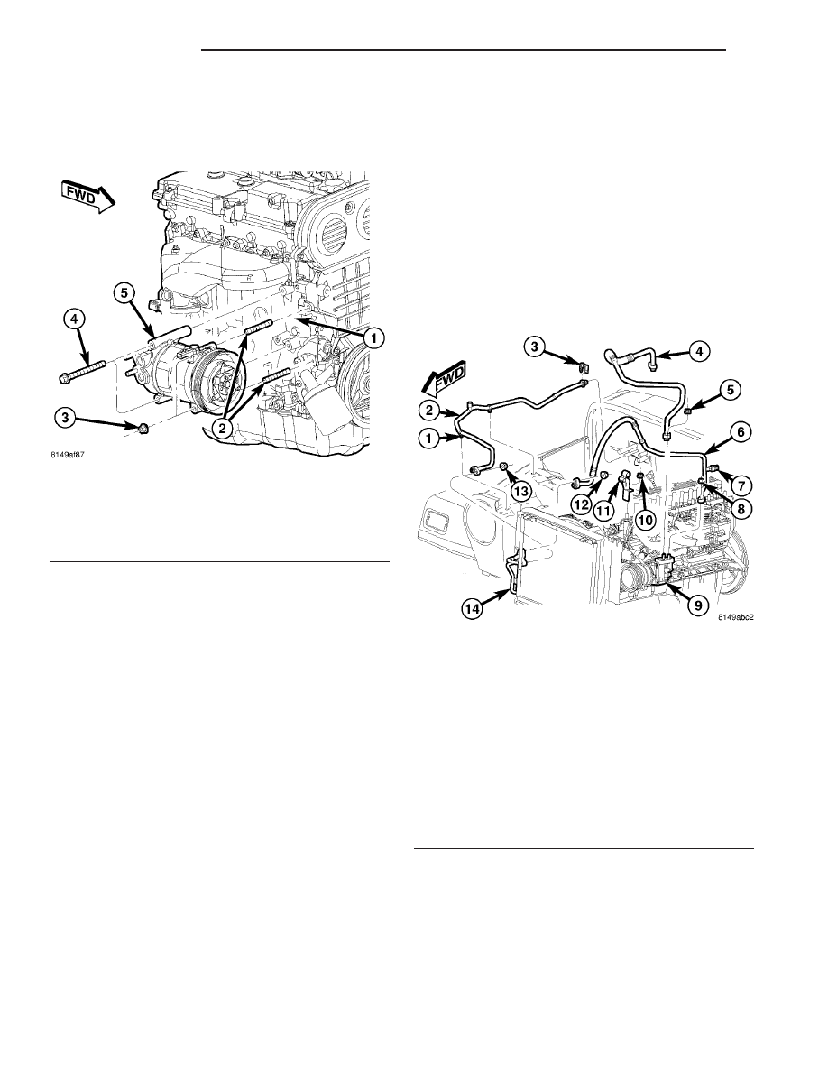
Fig. 5 A/C Compressor - 2.4L Engine

1 - CYLINDER BLOCK
2 - STUDS
3 - NUT (2)
4 - BOLT (2)
5 - A/C COMPRESSOR

Fig. 6 A/C Compressor Refrigerant Lines - 4.0L LHD

shown, RHD similar

1 - REFRIGERANT LINE RETAINING CLIP (2)
2 - A/C LIQUID LINE
3 - SECONDARY RETAINING CLIP
4 - A/C SUCTION LINE (FRONT SECTION)
5 - NUT
6 - A/C DISCHARGE LINE
7 - A/C HIGH PRESSURE SWITCH
8 - NUT
9 - A/C COMPRESSOR
10 - NUT
11 - REFRIGERANT LINE BRACKET
12 - NUT
13 - NUT
14 - A/C CONDENSER

24 - 66

PLUMBING

TJ

A/C COMPRESSOR (Continued)

(7) Remove the bolts and nuts that secure the A/C

compressor to the engine (Fig. 7).

(8) Remove the A/C compressor from the engine

compartment.

INSTALLATION

2.4L ENGINE

NOTE: If a replacement A/C compressor is being
installed, be certain to check the refrigerant oil
level. See Refrigerant Oil Level in this group for the
procedures. Use only refrigerant oil of the type rec-
ommended for the A/C compressor in the vehicle.

(1) Position the A/C compressor into the engine

compartment.

(2) Install the bolts and nuts that secure the A/C

compressor to the engine. Tighten the bolts and nuts
to 28 N·m (21 ft. lbs.).

(3) Remove the tape or plugs from the opened

refrigerant line fittings and compressor ports.

(4) Lubricate new rubber O-ring seals with clean

refrigerant oil and install them on the discharge and
liquid line fittings. Use only the specified O-rings as

they are made of a special material for the R-134a
system. Use only refrigerant oil of the type recom-
mended for the A/C compressor in the vehicle.

(5) Install the A/C suction and discharge lines onto

the A/C compressor.

(6) Install the nuts that secure the A/C suction

and discharge lines to the A/C compressor. Tighten
the nuts to 25 N·m (18 ft. lbs.).

(7) Connect the wire harness connector to the A/C

clutch field coil.

(8) Install the accessory drive belt (Refer to 7 -

COOLING/ACCESSORY

DRIVE/DRIVE

BELTS

-

INSTALLATION).

(9) Reconnect the negative battery cable.
(10) Evacuate the refrigerant system (Refer to 24 -

HEATING & AIR CONDITIONING/PLUMBING -
STANDARD PROCEDURE - REFRIGERANT SYS-
TEM EVACUATE).

(11) Charge the refrigerant system (Refer to 24 -

HEATING & AIR CONDITIONING/PLUMBING -
STANDARD PROCEDURE - REFRIGERANT SYS-
TEM CHARGE).

4.0L ENGINE

NOTE: If a replacement A/C compressor is being
installed, be certain to check the refrigerant oil
level. See Refrigerant Oil Level in this group for the
procedures. Use only refrigerant oil of the type rec-
ommended for the A/C compressor in the vehicle.

(1) Position the A/C compressor into the engine

compartment.

(2) Install the bolts and nut that secure the A/C

compressor to the engine.

• Tighten the bolts and nut fastening the compres-

sor to the cylinder block to 45-65 N·m (35-50 ft. lbs.).

• Tighten the bolts fastening the rear brace to the

compressor and cylinder block to 40-55 N·m (30-40 ft.
lbs.).

(3) Remove the tape or plugs from the opened

refrigerant line fittings and compressor ports.

(4) Lubricate new rubber O-ring seals with clean

refrigerant oil and install them on the discharge and
liquid line fittings. Use only the specified O-rings as
they are made of a special material for the R-134a
system. Use only refrigerant oil of the type recom-
mended for the A/C compressor in the vehicle.

(5) Install the A/C suction and discharge lines onto

the A/C compressor.

(6) Install the nuts that secure the A/C suction

and discharge lines to the A/C compressor. Tighten
the nuts to 25 N·m (18 ft. lbs.).

(7) Connect the wire harness connector to the A/C

clutch field coil.

Fig. 7 A/C Compressor - 4.0L Engine

1 - A/C COMPRESSOR
2 - NUT
3 - UPPER MOUNTING BRACKET
4 - CYLINDER BLOCK
5 - BOLT
6 - LOWER MOUNTING BRACKET
7 - BOLT
8 - BOLT
9 - COMPRESSOR LOWER MOUNTING POINT
10 - BOLT

TJ

PLUMBING

24 - 67

A/C COMPRESSOR (Continued)

(8) Install the accessory drive belt (Refer to 7 -

COOLING/ACCESSORY

DRIVE/DRIVE

BELTS

-

INSTALLATION).

(9) Reconnect the negative battery cable.
(10) Evacuate the refrigerant system (Refer to 24 -

HEATING & AIR CONDITIONING/PLUMBING -
STANDARD PROCEDURE - REFRIGERANT SYS-
TEM EVACUATE).

(11) Charge the refrigerant system (Refer to 24 -

HEATING & AIR CONDITIONING/PLUMBING -
STANDARD PROCEDURE - REFRIGERANT SYS-
TEM CHARGE).

A/C CONDENSER

DESCRIPTION

The A/C condenser is located in the front of the

engine compartment behind the grille (Fig. 8). The
A/C condenser is a heat exchanger that allows the
high-pressure refrigerant gas being discharged by the
A/C compressor to give up its heat to the air passing
over the condenser fins, which causes the refrigerant
to cool and change to a liquid state.

The A/C condenser is equipped with mounting pro-

visions and a tapping block for the A/C refrigerant
lines.

OPERATION

When air passes through the fins of the A/C con-

denser, the high-pressure refrigerant gas within the
A/C condenser gives up its heat. The refrigerant then
condenses as it leaves the A/C condenser and

becomes a high-pressure liquid. The volume of air
flowing over the condenser fins is critical to the
proper cooling performance of the A/C system. There-
fore, it is important that there are no objects placed
in front of the radiator grille openings at the front of
the vehicle or foreign material on the condenser fins
that might obstruct proper air flow. Also, any factory-
installed air seals or shrouds must be properly rein-
stalled following radiator or A/C condenser service.

The A/C condenser cannot be repaired and, if

faulty or damaged, it must be replaced.

REMOVAL

WARNING: Refer to the applicable warnings and
cautions for this system before performing the fol-
lowing operation (Refer to 24 - HEATING & AIR
CONDITIONING/PLUMBING - WARNINGS) and (Refer
to 24 - HEATING & AIR CONDITIONING/PLUMBING -
CAUTIONS). Failure to follow the warnings and cau-
tions could result in possible personal injury or
death.

CAUTION: Before removing the A/C condenser, note
the location of each of the radiator/condenser air
seals. These air seals are used to direct air through
the A/C condenser and radiator. The air seals must
be reinstalled in their proper locations in order for
the A/C and engine cooling systems to perform as
designed.

(1) Disconnect and isolate the negative battery

cable.

(2) Recover the refrigerant from the refrigerant

system (Refer to 24 - HEATING & AIR CONDITION-
ING/PLUMBING

-

STANDARD

PROCEDURE

-

REFRIGERANT SYSTEM RECOVERY).

(3) Partially

drain

the

engine

cooling

system

(Refer to 7 - COOLING - STANDARD PROCEDURE
- COOLING SYSTEM DRAINING).

(4) Remove the cooling recovery container (Refer to

7

-

COOLING/ENGINE/COOLANT

RECOVERY

CONTAINER - REMOVAL.

(5) Disconnect the upper radiator hose from the

radiator and position the hose out of the way (Refer
to 7 - COOLING - OPERATION - HOSE CLAMPS).

(6) Remove the radiator cooling fan and fan shroud

(Refer to 7 - COOLING/ENGINE/FAN DRIVE VIS-
COUS CLUTCH - REMOVAL).

(7) Raise and support the vehicle.
(8) Position the lower condenser/radiator air seal

out of the way and remove the two bolts that secure
the lower condenser mounting bracket to the bottom
of the grille panel.

(9) Lower the vehicle.

Fig. 8 A/C Condenser - Typical

1 - A/C CONDENSER
2 - MOUNTING BRACKET
3 - REFRIGERANT LINE TAPPING BLOCK

24 - 68

PLUMBING

TJ

A/C COMPRESSOR (Continued)

(10) If equipped, remove the upper condenser/radi-

ator air seal (Fig. 9).

(11) Remove the nuts that secure the discharge

and liquid lines to the condenser tapping block.

(12) Disconnect the discharge and liquid lines from

the condenser tapping block and remove and discard
the O-ring seals.

(13) Install plugs in, or tape over the opened

refrigerant line fittings and the condenser ports.

(14) Remove the two bolts that secure the upper

condenser mounting brackets to the top of the grille
panel.

(15) Remove the three bolts on each side of the

radiator that secure the radiator mounting brackets
to the grille panel.

(16) Tilt the radiator back towards the engine. Use

care to prevent damaging the radiator fins.

(17) Carefully remove the A/C condenser from the

engine compartment.

INSTALLATION

NOTE: If the A/C condenser is being replaced, add
22 milliliters (0.75 fluid ounce) of refrigerant oil to
the refrigerant system. Use only refrigerant oil of
the type recommended for the A/C compressor in
the vehicle.

(1) Carefully position the A/C condenser into the

engine compartment.

(2) Install the two bolts that secure the upper con-

denser mounting brackets to the top of the grille
panel. Tighten the bolts to 5 N·m (44 in. lbs.).

Fig. 9 A/C Condenser

1 - PUSH-PIN RETAINER
2 - UPPER AIR SEAL
3 - GRILLE PANEL
4 - AIR SEAL
5 - FRAME RAIL
6 - PUSH-PIN RETAINER
7 - LOWER AIR SEAL

8 - CONDENSER TAPPING BLOCK
9 - A/C CONDENSER
10 - REFRIGERANT LINE FITTING
11 - LIQUID LINE
12 - SERVICE PORT
13 - BOLTS
14 - AIR SEAL

TJ

PLUMBING

24 - 69

A/C CONDENSER (Continued)


Content   ..  598  599  600  601   ..