Jeep Wrangler TJ. Manual - part 592


  Index      Jeep     Jeep Wrangler TJ - service repair manual 2005 year


Search            


Content   ..  590  591  592  593   ..


Jeep Wrangler TJ. Manual - part 592


(1) Disconnect and isolate the negative battery

cable.

(2) Remove the glove box (Refer to 23 - BODY/IN-

STRUMENT PANEL/GLOVE BOX - REMOVAL).

(3) Remove the right front speaker bezel and

speaker

(Refer

to

8

-

ELECTRICAL/AUDIO/

SPEAKER - REMOVAL).

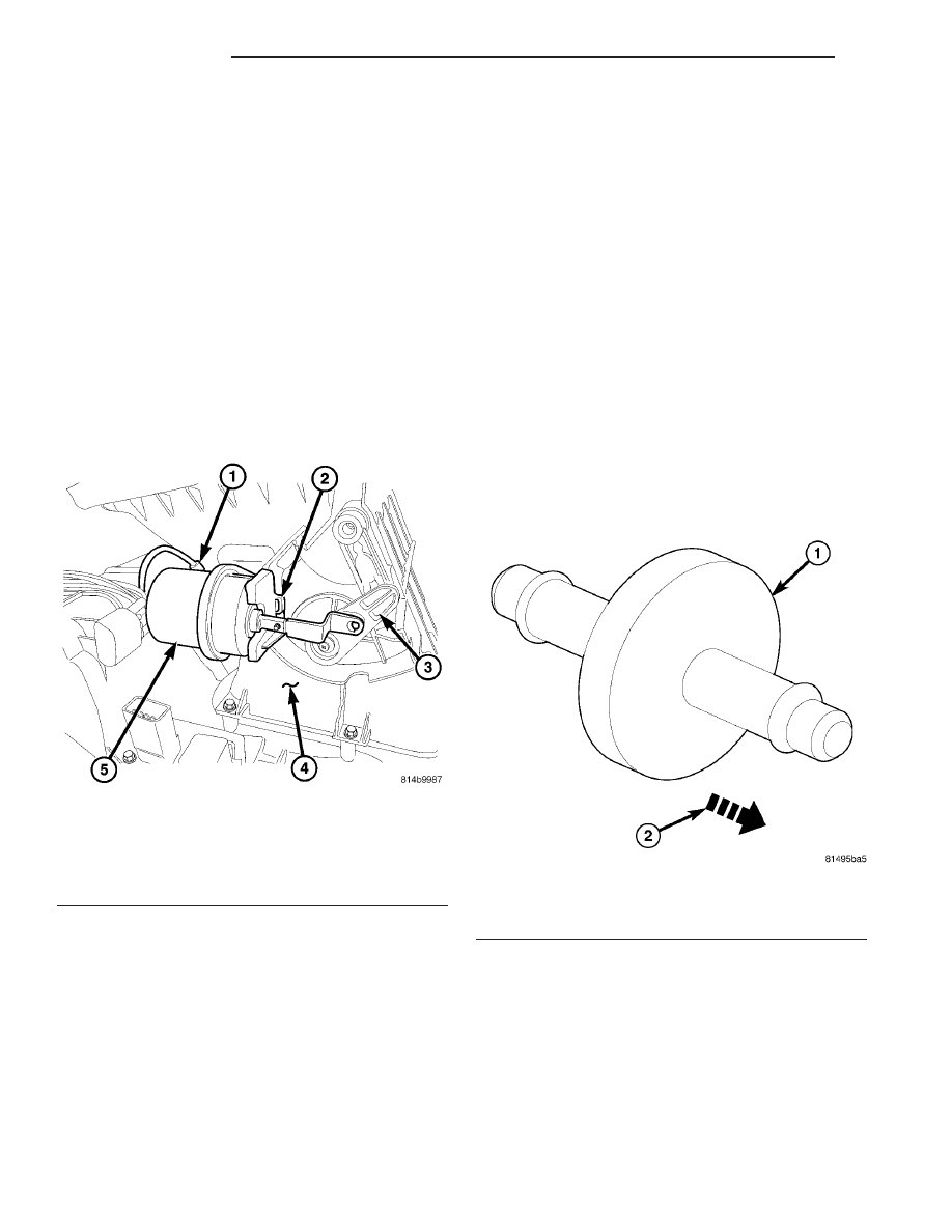
(4) Using a small flat bladed tool, gently pry the

actuator latch while pulling firmly outwards on the
actuator (Fig. 34). Rotate and tilt the actuator as
required to remove the actuator from the HVAC air
inlet housing mount.

(5) Disengage the actuator rod from the push-pin

type retainer located on the end of the recirculation
door actuator lever.

(6) Disconnect the vacuum harness from the recir-

culation door actuator and remove the actuator from
the vehicle.

INSTALLATION

NOTE: The recirculation-air door and actuator are
used only on models equipped with A/C.

(1) Connect the vacuum harness to the recircula-

tion door actuator.

(2) Engage the actuator rod to the push-pin type

retainer located on the end of the recirculation door
actuator lever.

(3) Rotate and tilt the recirculation door actuator

as required to install the actuator mount onto the
HVAC air inlet housing mounting boss. Push the

actuator onto the mount until it snaps into the
locked position.

(4) Install the right front speaker and speaker

bezel (Refer to 8 - ELECTRICAL/AUDIO/SPEAKER -
INSTALLATION).

(5) Install the glove box (Refer to 23 - BODY/IN-

STRUMENT PANEL/GLOVE BOX - INSTALLA-
TION).

(6) Reconnect the negative battery cable.

VACUUM CHECK VALVE

DESCRIPTION

Two vacuum check valves (Fig. 35) are installed in

the accessory vacuum supply system. One is on the
accessory vacuum supply line in the engine compart-
ment, near the vacuum tap on the engine intake
manifold. A second vacuum check valve is located at
the HVAC system takeout. The vacuum check valves
are designed to allow vacuum to flow in only one
direction through the vacuum supply circuits.

OPERATION

The use of the two vacuum check valves help to

maintain the system vacuum needed to retain the
selected A/C-heater mode settings. The check valves
prevent the engine from bleeding down system vac-
uum through the intake manifold during extended
heavy engine load (low engine vacuum) operation.

The vacuum check valves cannot be repaired and,

if faulty or damaged, must be replaced.

Fig. 34 Recirculation Door Actuator

1 - VACUUM HARNESS
2 - ACTUATOR LATCH
3 - RECIRCULATION DOOR ACTUATOR LEVER
4 - HVAC AIR INLET HOUSING
5 - RECIRCULATION DOOR ACTUATOR

Fig. 35 Vacuum Check Valve - Typical

1 - VACUUM CHECK VALVE
2 - DIRECTION OF AIR FLOW

24 - 34

CONTROLS

TJ

RECIRCULATION DOOR ACTUATOR (Continued)

REMOVAL

NOTE: Note the orientation of the check valves in
the vacuum supply line for correct reinstallation.

(1) Disconnect the vacuum check valve from the

fitting at the engine intake manifold and the acces-
sory vacuum supply line (Fig. 36) and remove the
valve.

(2) Disconnect the vacuum check valve from the

HVAC vacuum supply line fitting and the accessory
vacuum supply line and remove the valve.

INSTALLATION

(1) Using the orientation noted during Removal,

connect the vacuum check valve to the HVAC vac-
uum supply line fitting and the accessory vacuum
supply line.

(2) Using the orientation noted during Removal,

connect the vacuum check valve to the fitting at the
engine intake manifold and the accessory vacuum
supply line.

VACUUM RESERVOIR

DESCRIPTION

The vacuum reservoir (Fig. 37) is mounted to the

rear of the right front inner fender in the engine
compartment, under the battery tray.

The vacuum reservoir can be accessed for service

by removing the battery and battery tray.

OPERATION

Engine vacuum is stored in the vacuum reservoir.

The stored vacuum is used to operate the vacuum-
controlled vehicle accessories during periods of low
engine vacuum such as when the vehicle is climbing
a steep grade, or under other high engine load oper-
ating conditions.

The vacuum reservoir cannot be repaired and, if

faulty or damaged, it must be replaced.

Fig. 36 Vacuum Check Valves - Typical

1 - SCREW
2 - VACUUM CHECK VALVE (2)
3 - VACUUM LINE RETAINER (2)
4 - ACCESSORY VACUUM SUPPLY LINE
5 - ENGINE VACUUM FITTING
6 - HVAC VACUUM SUPPLY LINE
7 - INNER FENDER
8 - VACUUM RESERVOIR

Fig. 37 Vacuum Reservoir - Typical

1 - VACUUM RESERVOIR
2 - VACUUN LINE CONNECTION

TJ

CONTROLS

24 - 35

VACUUM CHECK VALVE (Continued)

REMOVAL

(1) Remove the battery and battery tray from the

engine compartment (Refer to 8 - ELECTRICAL/BAT-
TERY SYSTEM/BATTERY - REMOVAL) and (Refer
to 8 - ELECTRICAL/BATTERY SYSTEM/TRAY -
REMOVAL).

(2) Disconnect the vacuum supply line from the

vacuum reservoir (Fig. 38).

(3) Remove the screw that secures the vacuum res-

ervoir to the inner fender.

(4) Remove the vacuum reservoir from the engine

compartment.

INSTALLATION

(1) Position the vacuum reservoir into the engine

compartment.

(2) Install the screw that secures the vacuum res-

ervoir to the inner fender panel. Tighten the screw to
2 N·m (17 in. lbs.).

(3) Connect the vacuum supply line to the vacuum

reservoir.

(4) Install the battery tray and battery (Refer to 8

-

ELECTRICAL/BATTERY

SYSTEM/TRAY

-

INSTALLATION) and (Refer to 8 - ELECTRICAL/
BATTERY SYSTEM/BATTERY - INSTALLATION).

Fig. 38 Vacuum Reservoir - Typical

1 - SCREW
2 - VACUUM CHECK VALVE (2)
3 - VACUUM LINE RETAINER (2)
4 - ACCESSORY VACUUM SUPPLY LINE
5 - ENGINE VACUUM FITTING
6 - HVAC VACUUM SUPPLY LINE
7 - INNER FENDER
8 - VACUUM RESERVOIR

24 - 36

CONTROLS

TJ

VACUUM RESERVOIR (Continued)

DISTRIBUTION

TABLE OF CONTENTS

page

page

AIR OUTLETS

DESCRIPTION

. . . . . . . . . . . . . . . . . . . . . . . . . 37

REMOVAL

. . . . . . . . . . . . . . . . . . . . . . . . . . . . . 37

INSTALLATION

. . . . . . . . . . . . . . . . . . . . . . . . . 38

BLOWER MOTOR

DESCRIPTION

. . . . . . . . . . . . . . . . . . . . . . . . . 38

OPERATION

. . . . . . . . . . . . . . . . . . . . . . . . . . . 38

DIAGNOSIS AND TESTING

BLOWER MOTOR

. . . . . . . . . . . . . . . . . . . . . 38

REMOVAL

. . . . . . . . . . . . . . . . . . . . . . . . . . . . . 39

INSTALLATION

. . . . . . . . . . . . . . . . . . . . . . . . . 39

DEFROSTER DUCT

REMOVAL

. . . . . . . . . . . . . . . . . . . . . . . . . . . . . 40

INSTALLATION

. . . . . . . . . . . . . . . . . . . . . . . . . 40

FLOOR DISTRIBUTION DUCT

REMOVAL

. . . . . . . . . . . . . . . . . . . . . . . . . . . . . 40

INSTALLATION

. . . . . . . . . . . . . . . . . . . . . . . . . 40

HVAC HOUSING

DESCRIPTION

. . . . . . . . . . . . . . . . . . . . . . . . . 41

REMOVAL

HVAC HOUSING

. . . . . . . . . . . . . . . . . . . . . . 41

AIR INLET HOUSING

. . . . . . . . . . . . . . . . . . . 42

DISASSEMBLY

HVAC HOUSING

. . . . . . . . . . . . . . . . . . . . . . 43

AIR INLET HOUSING

. . . . . . . . . . . . . . . . . . . 47

ASSEMBLY

HVAC HOUSING

. . . . . . . . . . . . . . . . . . . . . . 48

AIR INLET HOUSING

. . . . . . . . . . . . . . . . . . . 51

INSTALLATION

HVAC HOUSING

. . . . . . . . . . . . . . . . . . . . . . 52

AIR INLET HOUSING

. . . . . . . . . . . . . . . . . . . 53

INSTRUMENT PANEL DEMISTER DUCTS

REMOVAL

. . . . . . . . . . . . . . . . . . . . . . . . . . . . . 53

INSTALLATION

. . . . . . . . . . . . . . . . . . . . . . . . . 54

INSTRUMENT PANEL DUCTS

REMOVAL

. . . . . . . . . . . . . . . . . . . . . . . . . . . . . 55

INSTALLATION

. . . . . . . . . . . . . . . . . . . . . . . . . 56

AIR OUTLETS

DESCRIPTION

There is one defroster air outlet located an the top

of the instrument panel (Fig. 1). The airflow from the
defroster outlet is directed by fixed vanes in the
defroster grille and cannot be adjusted. The defroster
outlet and grille are not serviceable from the instru-
ment panel top cover (Refer to 23 - BODY/INSTRU-
MENT PANEL/INSTRUMENT PANEL TOP COVER
- REMOVAL).

There are four instrument panel air outlets. One

air outlet is located near each outboard end of the
instrument panel facing the rear of the vehicle, and
two located near the top of the instrument panel cen-
ter bezel. Each of the instrument panel air outlets
contain a serviceable grille with movable vanes that
are used to direct or shut off the flow of the condi-
tioned air leaving the instrument panel outlets. The
instrument panel air outlets can be removed individ-
ually for service replacement.

REMOVAL

NOTE: The instrument panel air outlets are retained
to the pivots within the air outlet housings by a
snap fit.

(1) Using a trim stick C-4755 or equivalent (Fig.

2), gently pry the panel air outlet out of the panel
outlet housing as required.

Fig. 1 Air Outlets - LHD shown, RHD similar

1 - DEFROSTER AIR OUTLET
2 - INSTRUMENT PANEL TOP COVER
3 - INSTRUMENT PANEL
4 - INSTRUMENT PANEL AIR OUTLETS (4)
5 - INSTRUMENT PANEL CENTER BEZEL

TJ

DISTRIBUTION

24 - 37


Content   ..  590  591  592  593   ..