Jeep Wrangler TJ. Manual - part 559


  Index      Jeep     Jeep Wrangler TJ - service repair manual 2005 year


Search            


Content   ..  557  558  559  560   ..


Jeep Wrangler TJ. Manual - part 559


REAR SEAT BACK HINGE

REMOVAL

(1) Remove the seat. (Refer to 23 - BODY/SEATS/

REAR SEAT - REMOVAL)

(2) Remove the lower hinge bolts. (Fig. 16)
(3) Disconnect the lower j-straps of the seat back

and position aside the seat back cover.

(4) Disconnect the release cable. (Fig. 17)
(5) Remove the bolts and remove the hinge.

INSTALLATION

(1) Install the hinge and install the bolts.
(2) Tighten the bolts to 50 N·m (37 ft. lbs.).
(3) Connect the release cable.
(4) Connect the lower j-straps of the seat back.
(5) Install the lower hinge bolts and tighten to 50

N·m (37 ft. lbs.).

(6) Install the seat. (Refer to 23 - BODY/SEATS/

REAR SEAT - INSTALLATION)

REAR SEAT BACK COVER

REMOVAL

(1) Remove the seat. (Refer to 23 - BODY/SEATS/

SEAT - REMOVAL)

(2) Remove the screws and remove the seat back

release handle bezel. (Fig. 18)

(3) Release the j-clips at the bottom of the seat

back and remove the seat cover.

(4) Remove the hog rings and remove the seat

cushion. (Fig. 19)

INSTALLATION

(1) Position the cushion onto the seat back frame

and install new hog ring fasteners.

(2) Install the cover over the seat back frame and

cushion.

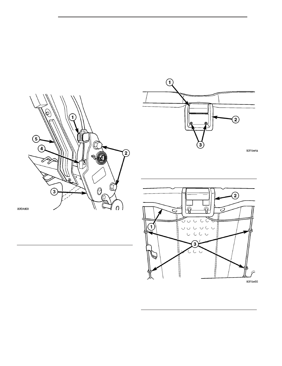
Fig. 17 REAR SEAT BACK HINGE

1 - RELEASE CABLE GUIDE
2 - BOLTS
3 - SEAT BACK HINGE
4 - RELEASE CABLE CONNECTION
5 - SEAT BACK FRAME

Fig. 18 RELEASE HANDLE

1 - RELEASE HANDLE
2 - BEZEL
3 - SCREWS (2)

Fig. 19 SEAT BACK CUSHION

1 - SEAT BACK FRAME
2 - SEAT BACK RELEASE HANDLE
3 - HOG RINGS (4)

23 - 78

SEATS

TJ

(3) Connect the bottom j-clips.
(4) Install the release handle bezel and install the

screws.

(5) Install the rear seat back. (Refer to 23 - BODY/

SEATS/REAR SEAT BACK - INSTALLATION)

REAR SEAT CUSHION COVER

REMOVAL

(1) Remove the rear seat back. (Refer to 23 -

BODY/SEATS/REAR SEAT BACK - REMOVAL)

(2) Un-zip the cover. (Fig. 20)
(3) Release the J-clips. (Fig. 21)
(4) Roll the cover from seat cushion and separate

from the seat cushion frame.

(5) Remove the hogrings from the foam to cover.

INSTALLATION

(1) Position the cover on the cushion, install new

hogrings to foam, and roll cover downward over the
corners.

(2) Connect the J-clips to the seat cushion frame.
(3) Close the cover zipper and tuck the zipper ends

into the cover.

(4) Install the rear seat back. (Refer to 23 - BODY/

SEATS/REAR SEAT BACK - INSTALLATION)

REAR SEAT RELEASE CABLE

REMOVAL

(1) Remove the seat. (Refer to 23 - BODY/SEATS/

REAR SEAT - REMOVAL)

(2) Remove the screws and remove the seat back

release handle bezel. (Fig. 18)

(3) Release the j-clips at the bottom of the seat

back and remove the seat cover.

(4) Disconnect the cables at the seat back hinges.

(Fig. 17)

(5) Position the seat back cushion aside and

remove the screws. (Fig. 22)

(6) Remove the seat back release cable assembly.

INSTALLATION

(1) Install the seat back release cable assembly

and install the screws.

(2) Connect the cables at the seat back hinges.
(3) Install the seat cover and engage the j-clips at

the bottom of the seat back.

(4) Install the handle bezel and install the screws.
(5) Install the seat. (Refer to 23 - BODY/SEATS/

REAR SEAT - INSTALLATION)

Fig. 20 SEAT CUSHION COVER

1 - SEAT CUSHION
2 - COVER ZIPPER

Fig. 21 SEAT CUSHION

1 - SEAT CUSHION FRAME
2 - J-STRAPS

Fig. 22 RELEASE CABLE ASSEMBLY

1 - SEAT BACK FRAME
2 - RELEASE CABLE ASSEMBLY HANDLE
3 - SCREWS

TJ

SEATS

23 - 79

REAR SEAT BACK COVER (Continued)

REAR SEAT STRIKERS

REMOVAL

Rear Strikers

(1) Release the seat back and fold seat assembly

forward.

(2) Remove the bolts and remove the striker. (Fig.

23)

Front Strikers

(1) Remove the seat. (Refer to 23 - BODY/SEATS/

REAR SEAT - REMOVAL)

(2) Remove the bolts and remove the striker. (Fig.

23)

INSTALLATION

Front Strikers

(1) Install the striker and install the bolts.
(2) Tighten the bolts to 61 N·m (45 ft. lbs.).
(3) Install the seat. (Refer to 23 - BODY/SEATS/

REAR SEAT - INSTALLATION)

Rear Strikers

(1) Install the striker and install the bolts.
(2) Tighten the bolts to 61 N·m (45 ft. lbs.).

(3) Return the seat to the down position.

Fig. 23 REAR SEAT STRIKERS

1 - FRONT STRIKER
2 - BOLTS (2 PER STRIKER)
3 - REAR STRIKER

23 - 80

SEATS

TJ

STATIONARY GLASS

TABLE OF CONTENTS

page

page

STATIONARY GLASS

DESCRIPTION

WINDSHIELD SAFETY PRECAUTIONS

. . . . . 81

QUARTER GLASS

REMOVAL

. . . . . . . . . . . . . . . . . . . . . . . . . . . . . 82

INSTALLATION

. . . . . . . . . . . . . . . . . . . . . . . . . 82

WINDSHIELD

REMOVAL

. . . . . . . . . . . . . . . . . . . . . . . . . . . . . 83

INSTALLATION

. . . . . . . . . . . . . . . . . . . . . . . . . 83

WINDSHIELD HINGE

REMOVAL

. . . . . . . . . . . . . . . . . . . . . . . . . . . . . 84

INSTALLATION

. . . . . . . . . . . . . . . . . . . . . . . . . 84

WINDSHIELD FRAME

REMOVAL

. . . . . . . . . . . . . . . . . . . . . . . . . . . . . 85

INSTALLATION

. . . . . . . . . . . . . . . . . . . . . . . . . 85

STATIONARY GLASS

DESCRIPTION

WINDSHIELD SAFETY PRECAUTIONS

DESCRIPTION

WARNING:

DO

NOT

OPERATE

THE

VEHICLE

WITHIN 24 HOURS OF WINDSHIELD INSTALLATION.
IT TAKES AT LEAST 24 HOURS FOR URETHANE
ADHESIVE TO CURE. IF IT IS NOT CURED, THE
WINDSHIELD MAY NOT PERFORM PROPERLY IN
AN ACCIDENT.

URETHANE ADHESIVES ARE APPLIED AS A

SYSTEM. USE GLASS CLEANER, GLASS PREP
SOLVENT, GLASS PRIMER, PVC (VINYL) PRIMER
AND PINCH WELD (FENCE) PRIMER PROVIDED BY
THE ADHESIVE MANUFACTURER. IF NOT, STRUC-
TURAL INTEGRITY COULD BE COMPROMISED.

DAIMLERCHRYSLER DOES NOT RECOMMEND

GLASS

ADHESIVE

BY

BRAND.

TECHNICIANS

SHOULD REVIEW PRODUCT LABELS AND TECHNI-
CAL DATA SHEETS, AND USE ONLY ADHESIVES
THAT THEIR MANUFACTURES WARRANT WILL
RESTORE A VEHICLE TO THE REQUIREMENTS OF
FMVSS 212. TECHNICIANS SHOULD ALSO INSURE
THAT PRIMERS AND CLEANERS ARE COMPATIBLE
WITH THE PARTICULAR ADHESIVE USED.

BE SURE TO REFER TO THE URETHANE MAN-

UFACTURER’S DIRECTIONS FOR CURING TIME
SPECIFICATIONS, AND DO NOT USE ADHESIVE
AFTER ITS EXPIRATION DATE.

VAPORS THAT ARE EMITTED FROM THE URE-

THANE ADHESIVE OR PRIMER COULD CAUSE
PERSONAL INJURY. USE THEM IN A WELL-VENTI-
LATED AREA.

SKIN CONTACT WITH URETHANE ADHESIVE

SHOULD BE AVOIDED. PERSONAL INJURY MAY
RESULT.

ALWAYS WEAR EYE AND HAND PROTECTION

WHEN WORKING WITH GLASS.

CAUTION: Protect all painted and trimmed surfaces
from coming in contact with urethane or primers.
Be careful not to damage painted surfaces when
removing moldings or cutting urethane around
windshield.

OPERATION

The windshield is attached to the window frame

with urethane adhesive. The urethane adhesive is
applied cold and seals the surface area between the
window opening and the glass. The primer adheres
the urethane adhesive to the windshield.

It is difficult to salvage a windshield during the

removal operation. The windshield is part of the
structural support for the roof. The urethane bonding
used to secure the windshield to the fence is difficult
to cut or clean from any surface. If the moldings are
set in urethane, it would also be unlikely they could
be salvaged. Before removing the windshield, check
the availability of the windshield and moldings from
the parts supplier.

TJ

STATIONARY GLASS

23 - 81


Content   ..  557  558  559  560   ..