Jeep Wrangler TJ. Manual - part 555


  Index      Jeep     Jeep Wrangler TJ - service repair manual 2005 year


Search            


Content   ..  553  554  555  556   ..


Jeep Wrangler TJ. Manual - part 555


WINDSHIELD HEADER

REMOVAL

(1) Position both sun visors out.
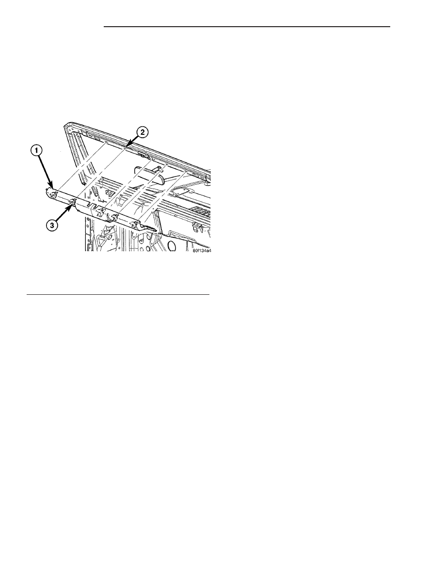
(2) Using a trim stick C-4755 or equivalent, sepa-

rate the retaining clips and remove the trim from
behind the a-pillar trim panels. (Fig. 16)

INSTALLATION

(1) Install the windshield header trim and position

the end tabs behind the a-pillar trim.

(2) Seat the retaining clips fully.

SPORT BAR - SPEAKER POD

REMOVAL

(1) On vehicles equipped with a soft top, unzip the

side panel next to the pod.

(2) On vehicles equipped with a hard top, unclip

the windshield clamps.

(3) Remove the bolts on side of the top next to the

pod and loosen the opposite side bolts. (Refer to 23 -
BODY/REMOVEABLE

TOP/HARD

TOP

-

REMOVAL)

(4) Lift up the side of the top to gain access to the

pod bolts and support with a block of wood or similar.

(5) Remove the two bolts securing the pod to the

sport bar.

(6) Separate the pod guide pin from the sport bar

and disconnect the electrical connector.

INSTALLATION

(1) Connect the pod electrical connector and install

the pod onto the guide pin.

(2) Install the bolts and tighten to 68 N·m (50 ft.

lbs.).

(3) On vehicles equipped with a hard top, install

the hard top. (Refer to 23 - BODY/REMOVABLE
TOP/HARD TOP - INSTALLATION)

(4) On vehicles equipped with a soft top, zip up the

side panel.

Fig. 16 WINDSHIELD HEADER MOLDING

1 - WINDSHIELD HEADER TRIM
2 - WINDSHIELD FRAME
3 - SPRING CLIPS (4)

23 - 62

INTERIOR

TJ

PAINT

TABLE OF CONTENTS

page

page

PAINT

SPECIFICATIONS - PAINT CODES

. . . . . . . . . . 63

PAINT CODE

DESCRIPTION

. . . . . . . . . . . . . . . . . . . . . . . . . 63

BASECOAT/CLEARCOAT FINISH

DESCRIPTION

. . . . . . . . . . . . . . . . . . . . . . . . . 64

PAINT TOUCH-UP

STANDARD PROCEDURE - PAINT TOUCH-UP

. 64

FINESSE SANDING, BUFFING & POLISHING

DESCRIPTION

. . . . . . . . . . . . . . . . . . . . . . . . . 64

PAINT

SPECIFICATIONS - PAINT CODES

NOTE: Because of late model changes to the avail-
able paint colors (Refer to VEHICLE DATA/VEHICLE
INFORMATION/VEHICLE CERTIFICATION LABEL -
DESCRIPTION) or (Refer to VEHICLE DATA/VEHI-
CLE INFORMATION/BODY CODE PLATE - DESCRIP-
TION) for the correct paint codes for each vehicle.
(Refer to 23 - BODY/PAINT/PAINT CODE - DESCRIP-
TION)

EXTERIOR COLORS

EXTERIOR COLOR

DAIMLERCHRYSLER

CODE

Flame Red Clearcoat

PR4

Impact Orange Clearcoat

BV5

Light Khaki Pearlcoat

AJC

Electric Lime Green

Pearlcoat

BGL

Deep Beryl Green

Pearlcoat

CGV

Moss Green Pearlcoat

RJN

Patriot Blue Pearlcoat

WBT

Bright Silver Metallic

Clearcoat

WSB

Black Clearcoat

DX8

Stone White

SW1

INTERIOR COLORS

INTERIOR COLOR

DAIMLERCHRYSLER

CODE

Dark Slate Gray

DV

Khaki

J3

EXTERIOR HARD AND SOFT TOP COLORS

EXTERIOR HARD TOP

COLORS

DAIMLERCHRYSLER

CODE

Medium Gray

BDL

Dark Khaki

ZJ8

PAINT CODE

DESCRIPTION

Exterior vehicle body colors are identified on the

Vehicle

Certification

Label

(Refer

to

VEHICLE

DATA/VEHICLE INFORMATION/VEHICLE CERTI-
FICATION LABEL - DESCRIPTION) or the Body
Code Plate (Refer to VEHICLE DATA/VEHICLE
INFORMATION/BODY CODE PLATE - DESCRIP-
TION). The first digit of the paint code listed on the
vehicle indicates the sequence of application, i.e.: P =
primary coat, Q = secondary coat. The color names
provided in the Paint and Trim Code Description
chart are the color names used on most repair prod-
uct containers. (Refer to 23 - BODY/PAINT - SPECI-
FICATIONS)

TJ

PAINT

23 - 63

BASECOAT/CLEARCOAT
FINISH

DESCRIPTION

On most vehicles a two-stage paint application

(basecoat/clearcoat) is used. Color that is applied to
primer is called basecoat. The clearcoat protects the
basecoat from ultraviolet light and provides a dura-
ble high-gloss finish.

PAINT TOUCH-UP

STANDARD PROCEDURE - PAINT TOUCH-UP

When a painted metal surface has been scratched

or chipped, it should be touched-up as soon as possi-
ble to avoid corrosion. For best results, use Mopar

t

Scratch Filler/Primer, Touch-Up Paints and Clear
Topcoat. Refer to Introduction group of this manual
for Body Code Plate information.

WARNING: USE AN OSHA APPROVED RESPIRATOR
AND SAFETY GLASSES WHEN SPRAYING PAINT
OR SOLVENTS IN A CONFINED AREA. PERSONAL
INJURY CAN RESULT.

(1) Scrape loose paint and corrosion from inside

scratch or chip.

(2) Clean affected area with Mopar

t Tar/Road Oil

Remover, and allow to dry.

(3) Fill the inside of the scratch or chip with a coat

of filler/primer. Do not overlap primer onto good sur-
face finish. The applicator brush should be wet
enough to puddle-fill the scratch or chip without run-
ning. Do not stroke brush applicator on body surface.
Allow the filler/primer to dry hard.

(4) Cover the filler/primer with color touch-up

paint. Do not overlap touch-up color onto the original
color coat around the scratch or chip. Butt the new

color to the original color, if possible. Do not stroke
applicator brush on body surface. Allow touch-up
paint to dry hard.

(5) On vehicles without clear coat, the touch-up

color can be lightly finesse sanded (1500 grit) and
polished with rubbing compound.

(6) On vehicles with clearcoat, apply clear topcoat

to touch-up paint with the same technique as
described in Step 4. Allow clear topcoat to dry hard.
If desired, Step 5 can be performed on clear topcoat.

WARNING: AVOID PROLONGED SKIN CONTACT
WITH PETROLEUM OR ALCOHOL – BASED CLEAN-
ING SOLVENTS. PERSONAL INJURY CAN RESULT.
AVOID PROLONGED SKIN CONTACT WITH PETRO-
LEUM OR ALCOHOL – BASED CLEANING SOL-
VENTS. PERSONAL INJURY CAN RESULT.

FINESSE SANDING, BUFFING
& POLISHING

DESCRIPTION

CAUTION: Do not remove more than .5 mils of
clearcoat finish, if equipped. Basecoat paint must
retain clearcoat for durability.
Use a Paint Thickness Gauge #PR-ETG-2X or equiv-
alent to determine film thickness before and after
the repair.

Minor acid etching, orange peel, or smudging in

clearcoat or single-stage finishes can be reduced with
light finesse sanding, hand buffing, and polishing. If
the finish has been finesse sanded in the past,
it cannot be repeated. Finesse sanding opera-
tion should be performed by a trained automo-
tive paint technician.

23 - 64

PAINT

TJ

REMOVEABLE TOP

TABLE OF CONTENTS

page

page

REMOVEABLE TOP

STANDARD PROCEDURE

HARD TOP REPAIR

. . . . . . . . . . . . . . . . . . . . 65

HARD TOP REPAIR

. . . . . . . . . . . . . . . . . . . . 65

HARD TOP FRACTURE REPAIR

. . . . . . . . . . 66

HARD TOP SAG REPAIR

. . . . . . . . . . . . . . . . 66

HARD TOP

REMOVAL

. . . . . . . . . . . . . . . . . . . . . . . . . . . . . 67

INSTALLATION

. . . . . . . . . . . . . . . . . . . . . . . . . 67

SOFT TOP

REMOVAL

. . . . . . . . . . . . . . . . . . . . . . . . . . . . . 68

INSTALLATION

. . . . . . . . . . . . . . . . . . . . . . . . . 68

SOFT TOP FABRIC

REMOVAL

. . . . . . . . . . . . . . . . . . . . . . . . . . . . . 69

INSTALLATION

. . . . . . . . . . . . . . . . . . . . . . . . . 69

DOOR OPENING FRAME

REMOVAL

. . . . . . . . . . . . . . . . . . . . . . . . . . . . . 70

INSTALLATION

. . . . . . . . . . . . . . . . . . . . . . . . . 70

HARD/SOFT TOP LATCH

REMOVAL

. . . . . . . . . . . . . . . . . . . . . . . . . . . . . 70

INSTALLATION

. . . . . . . . . . . . . . . . . . . . . . . . . 70

REMOVEABLE TOP

STANDARD PROCEDURE

HARD TOP REPAIR

NOTE: The hard top is manufactured from a sheet
molded compound (SMC).
SMC is constructed using short fiberglass strands
usually less than 5.08 cm (2 inches) long. Sheet
stock of glass impregnated resin matting is placed
into the mold and pressed under heat to flow mate-
rial throughout the mold. Tooling is shear edge
designed to mold to net (i.e. no trimming at periph-
ery required).
SMC is repairable in accordance with established
procedures described within this manual. (Refer to
23 - BODY - STANDARD PROCEDURE - PLASTIC
BODY PANEL REPAIR)

Hard Top Locators

There are two hard top locator devices positioned

approximately 150 mm (6 in.) from the most forward
attachment holes. If the locator device is missing or
damaged it must be replaced, as it will assist in plac-
ing the hard top back into the correct position for top
re-attachment.

If the locator device is missing just make sure that

the attachment holes are clear and simply insert the
new locator (part is orientated by hole size and
inserts from the bottom of the rail before the hard
top is re-attached to the vehicle).

If the locator device is damaged, cut off the locking

tabs, remove and replace as described above.

HARD TOP REPAIR

If it has been determined that the hard top can be

repaired. The following required materials and proce-
dures are to be used.

(1) Use a grinder to remove the paint and outline

the damaged area. Use a grade 150 grit disc for paint
removal.

(2) Grind the outlined surface area again with a

240 grit disc to prevent coarse scratches from appear-
ing in the final finish.

(3) If cracks extend from the hole, it will be neces-

sary to stop-drill the crack(s) with a 3-mm (1/8-in)
diameter drill bit. This will prevent the crack from
spreading and allow repair material to be effective.

(4) Position a fiberglass mat or cloth on the repair

surface area. Cut the mat 2.5 cm (1 in.) larger than
repair area but smaller than the outline area. Make
the outline area larger if required.

(5) Clean the outlined area.
(6) Place the fiberglass cloth on aluminum foil.
(7) Pour the fiberglass resin into a clean container.
(8) Mix the appropriate amount of hardener and

resin. Follow the manufacturers instructions.

(9) Apply the hardener/resin mixture to both sides

of the fiberglass cloth.

(10) Place the fiberglass cloth over the repair area.

Next, place the aluminum foil over the cloth using a
plastic spreader to smooth-out the cloth and resin.
Use firm pressure to remove air bubbles and to
smooth-out the cloth. Remove the aluminum foil.

(11) Allow the resin to cure.
(12) Smooth-out the surface area to the contour of

the hard top with a 150-grit disc.

(13) Apply plastic filler to complete the repair. Fin-

ish smoothing the surface area with 240-320 grit
paper.

TJ

REMOVEABLE TOP

23 - 65


Content   ..  553  554  555  556   ..