Jeep Wrangler TJ. Manual - part 526


  Index      Jeep     Jeep Wrangler TJ - service repair manual 2005 year


Search            


Content   ..  524  525  526  527   ..


Jeep Wrangler TJ. Manual - part 526


REAR OUTPUT SHAFT SEAL

REMOVAL

(1) Shift the transmission and transfer case into

NEUTRAL.

(2) Raise and support vehicle.
(3) Mark a line across the pinion shaft and at each

end of the propeller shaft for installation reference.

(4) Remove the U-joint strap bolts at the pinion

shaft yoke.

(5) Pry open clamp holding the dust boot to propel-

ler shaft yoke (Fig. 87).

(6) Slide the slip yoke off of the transmission/

transfer case output shaft and remove the propeller
shaft.

(7) Spread band clamp which holds output shaft

boot to the output shaft slinger, or output shaft
damper, with a suitable awl, or equivalent.

NOTE: Vehicles built with a 4.0L engine and a man-
ual transmission use a damper weight on the trans-
fer case output shaft. Be sure to identify the
transfer case before proceeding.

(8) Remove output shaft boot from slinger, or out-

put shaft damper, and output shaft.

(9) If the vehicle is not equipped with an output

shaft damper, remove the output shaft rear slinger
using Puller MD-998056-A (Fig. 88).

(10) If the vehicle is equipped with an output shaft

damper, use Screws 8421 and the puller yoke and
forcing screw from a bolt-grip puller set, such as
those used to remove steering wheels and harmonic
balancers, to remove the transfer case output shaft
damper.

(11) Use a suitable pry tool, or a slide hammer

mounted screw, to remove the seal from the rear
retainer (Fig. 89).

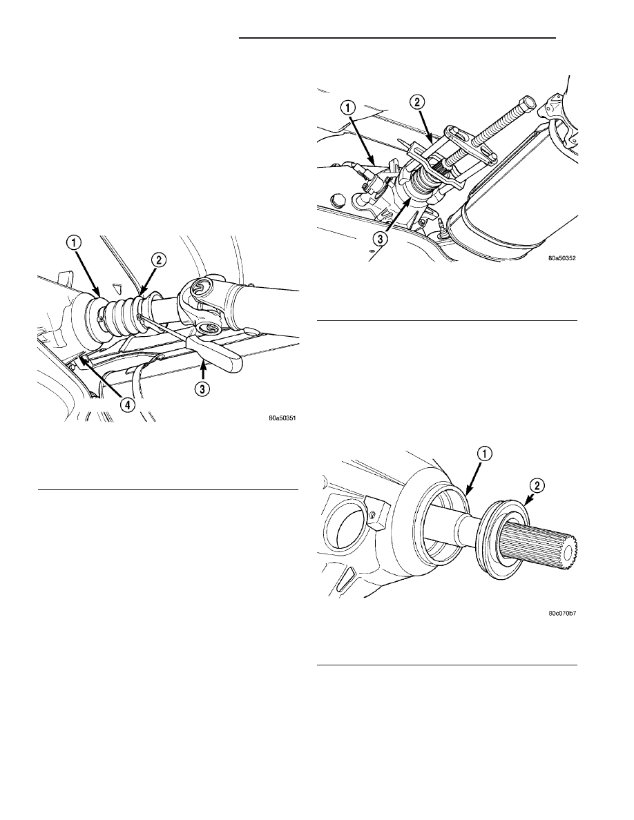
Fig. 87 Dust Boot Clamp

1 - SLINGER
2 - BOOT
3 - AWL
4 - TRANSFER CASE

Fig. 88 Rear Slinger Removal

1 - TRANSFER CASE
2 - SPECIAL TOOL MD-998056-A
3 - SLINGER

Fig. 89 Rear Output Shaft Seal

1 - REAR RETAINER
2 - OUTPUT SHAFT SEAL

21 - 194

TRANSFER CASE - NV231

TJ

INSTALLATION

(1) Apply liberal quantity of petroleum jelly to new

rear seal and to output shaft. Petroleum jelly is
needed to protect seal lips during installation.

(2) Slide seal onto Seal Protector 6992 (Fig. 90).

Slide seal protector and seal onto output shaft.

(3) Slide Installer C-4076-B onto seal protector

with the recessed side of the tool toward the seal.
Drive seal into rear bearing retainer with Installer
C-4076-B and Handle MD-998323 (Fig. 91).

NOTE: Vehicles built with a 4.0L engine and a man-
ual transmission use a damper weight on the trans-
fer case output shaft. Be sure to identify the
transfer case before proceeding.

(4) Install a new output shaft rear slinger with

Installer 8408, if the vehicle is not equipped with an
output shaft damper.

(5) If the vehicle is equipped with an output shaft

damper, install the output shaft damper as follows:

(a) Position the damper weight on the output

shaft. Start the damper onto the output shaft
chamfer, being careful to keep the weight square to
the output shaft. (Fig. 92)

(b) Position the driver portion of Installer 8422

(Fig. 93) onto the damper, making sure the legs of
the damper are positioned through the slots of the
damper.

Fig. 92 Position Damper on Output Shaft

1 - Transfer Case
2 - Output Shaft
3 - Damper Weight
4 - Chamfer

Fig. 93 Driver Installer 8422

1 - Pulling Screw
2 - Pulling Screw Nut
3 - Bearing
4 - Driver Legs
5 -Installer Driver

Fig. 90 Output Shaft Seal and Protector

1 - OUTPUT SHAFT SEAL
2 - SPECIAL TOOL 6992
3 - TRANSFER CASE

Fig. 91 Rear Seal Installation

1 - SPECIAL TOOL C-4076-B
2 - SPECIAL TOOL MD-998323
3 - TRANSFER CASE

TJ

TRANSFER CASE - NV231

21 - 195

REAR OUTPUT SHAFT SEAL (Continued)

(c) Thread the puller screw of Installer 8422 into

the output shaft by hand only. Make sure the
screw is fully threaded into the output shaft.

(d) Using a wrench to hold the pulling screw sta-

tionary (Fig. 94), turn the pulling screw nut until
the driver legs contact the rear face of the transfer
case rear retainer. When the legs contact the
retainer, the damper is properly positioned on the
output shaft.

(6) Install boot on output shaft slinger, or output

shaft damper, and crimp retaining clamp with tool
C-4975-A (Fig. 95).

(7) Slide the slip yoke on the transmission/transfer

case output shaft. Align installation reference marks
at the axle yoke and install the propeller shaft.

(8) Tighten the U-joint strap/clamp bolts at the

axle yoke to 19 N·m (14 ft. lbs.).

(9) Crimp clamp with Clamp Tool C-4975A to hold

dust boot to propeller shaft yoke.

(10) Remove support and lower the vehicle.

SHIFT LEVER

REMOVAL

(1) Shift transfer case into 4L.
(2) Raise vehicle.
(3) Loosen adjusting trunnion locknut and slide

shift rod out of trunnion (Fig. 96). If rod lacks
enough travel to come out of trunnion, push trunnion
out of torque shaft.

(4) Lower vehicle.
(5) Remove console. (Refer to 23 - BODY/INTERI-

OR/FLOOR CONSOLE - REMOVAL)

(6) Remove screws attaching lever assembly to

floorpan and remove assembly and shift rod (if left
attached).

INSTALLATION

(1) If shift rod was not removed from lever assem-

bly, work rod down through floorpan opening. Then
position lever assembly on floorpan and install
assembly attaching screws.

(2) Install console. (Refer to 23 - BODY/INTERI-

OR/FLOOR CONSOLE - INSTALLATION)

(3) Raise vehicle.
(4) Connect trunnion to torque shaft arm. Or, slide

shift rod into trunnion on range lever. Be sure shift
rod slides freely in trunnion.

(5) Verify that range lever is in 4L position. Then

tighten trunnion lock bolt.

(6) Lower vehicle and check transfer case shift

operation.

Fig. 94 Install Damper

1 - Damper
2 - Installer Driver
3 - Pulling Screw Nut
4 - Pulling Screw

Fig. 95 Slinger Boot Installation - Typical

1 - SPECIAL TOOL C-4975–A
2 - SLINGER
3 - BOOT
4 - CLAMP

21 - 196

TRANSFER CASE - NV231

TJ

REAR OUTPUT SHAFT SEAL (Continued)

Fig. 96 Shift Linkage

1 - Rivnut (4)

8 - Torque Shaft

2 - Shift Lever Assembly

9 - Transfer Case Shift Lever

3 - Floorpan

10 - Torque Shaft Transfer Case Bracket

4 - Trunnion Lock Bolt

A - 3-4 N·m (27-35 in. lbs.)

5 - Selector Rod and Trunnion

B - 11-14 N·m (97-123 in. lbs.)

6 - Shift Lever Rod

C - 8-14 N·m (72-120 in. lbs.)

7 - Torque Shaft Frame Bracket

TJ

TRANSFER CASE - NV231

21 - 197

SHIFT LEVER (Continued)


Content   ..  524  525  526  527   ..