Jeep Wrangler TJ. Manual - part 524


  Index      Jeep     Jeep Wrangler TJ - service repair manual 2005 year


Search            


Content   ..  522  523  524  525   ..


Jeep Wrangler TJ. Manual - part 524


(11) Install new O-ring on detent plug (Fig. 68).
(12) Lubricate detent plunger with transmission

fluid or light coat of petroleum jelly.

(13) Install detent plunger, spring and plug (Fig.

68).

(14) Verify that plunger is properly engaged in sec-

tor.

FRONT OUTPUT SHAFT AND DRIVE CHAIN

(1) Lubricate front output shaft-sprocket assembly,

drive chain, and drive sprocket with transmission
fluid.

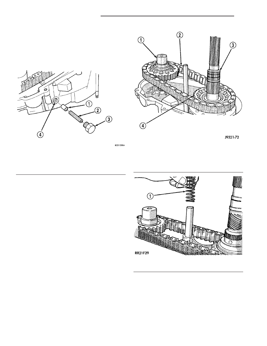
(2) Assemble drive chain and front output shaft

(Fig. 69).

(3) Start chain on mainshaft drive sprocket.
(4) Guide front shaft into bearing and drive

sprocket onto mainshaft drive gear (Fig. 69).

(5) Install mode spring on upper end of mode fork

shift rail (Fig. 70).

Fig. 68 Shift Detent Components

1 - POPPET
2 - SPRING
3 - SCREW
4 - POPPET BORE (IN CASE)

Fig. 69 Installing Drive Chain And Front Output

Shaft

1 - FRONT OUTPUT SHAFT
2 - DRIVE CHAIN
3 - MAINSHAFT
4 - DRIVE SPROCKET

Fig. 70 Install Mode Fork Spring

1 - MODE SPRING

21 - 186

TRANSFER CASE - NV231

TJ

TRANSFER CASE - NV231 (Continued)

OIL PUMP AND REAR CASE

(1) Install magnet in front case pocket (Fig. 71).
(2) Assemble oil pickup screen, connecting hose,

and tube.

(3) Install new pickup tube O-ring in oil pump

(Fig. 72).

(4) Insert oil pickup tube in oil pump inlet.
(5) Position assembled oil pump and pickup tube

in rear case. Be sure pickup screen is securely seated
in case slot. Also be sure oil pump locating tabs are
outside rear case (Fig. 73).

(6) Apply 3 mm (1/8 in.) wide bead of Mopar

t gas-

ket maker or silicone adhesive sealer to mounting
flange of front case. Work sealer bead around bolt
holes.

(7) Lift rear case and oil pump and carefully posi-

tion assembly on front case. Be sure case dowels are

aligned and that mode fork rail extends through rear
case before seating rear case on front case.

(8) Install case attaching bolts. Alignment bolts at

each end of case are only ones requiring washers
(Fig. 74).

(9) Tighten case bolts to 27-34 N·m (20-25 ft. lbs.)

torque.

YOKE AND RANGE LEVER

(1) Install indicator switch in front case. Tighten

switch to 20-34 N·m (15-25 ft. lbs.) torque.

(2) Install range lever, washer and locknut on sec-

tor shaft (Fig. 75). Tighten locknut to 27-34 N·m
(20-25 ft. lbs.) torque.

(3) Install new seal washer on front output shaft

(Fig. 77).

(4) Lubricate yoke hub with transmission fluid and

install yoke on front shaft.

(5) Install new seal washer on front shaft.
(6) Install yoke and new yoke nut on front output

shaft (Fig. 76).

(7) Tighten yoke nut to 122-176 N·m (90-130 ft.

lbs.) torque. Use Tool C-3281, or similar tool to hold
yoke while tightening yoke nut.

Fig. 71 Installing Case Magnet

1 - MAGNET

Fig. 72 Pickup Tube O-Ring Position

1 - OIL PUMP
2 - O-RING

Fig. 73 Oil Pump And Pickup Tube Installation

1 - OIL PUMP
2 - PICKUP TUBE
3 - PICKUP SCREEN AND CONNECTOR

Fig. 74 Alignment Bolt Location

1 - ALIGNMENT BOLT AND WASHER (AT EACH END OF CASE)

TJ

TRANSFER CASE - NV231

21 - 187

TRANSFER CASE - NV231 (Continued)

REAR RETAINER

(1) Apply bead of Mopar

t Sealer P/N 82300234, or

Loctite™ Ultra Gray, to mating surface of rear

retainer. Sealer bead should be a maximum of 3/16
inch.

(2) Install rear retainer on rear case. Tighten

retainer bolts to 20-27 N·m (15-20 ft. lbs.) torque.

(3) Install rear bearing I.D. retaining ring and

spacer on output shaft.

(4) Apply liberal quantity of petroleum jelly to new

rear seal and to output shaft. Petroleum jelly is
needed to protect seal lips during installation.

(5) Slide seal onto Seal Protector 6992 (Fig. 78).

Slide seal protector and seal onto output shaft.

(6) Slide Installer C-4076-B onto seal protector

with the recessed side of the tool toward the seal.
Drive seal into rear bearing retainer with Installer
C-4076-B and Handle MD-998323 (Fig. 79).

Fig. 75 Range Lever Installation

1 - RANGE LEVER
2 - WASHER
3 - LOCKNUT

Fig. 76 Output Shaft Yoke Installation

1 - OUTPUT SHAFT YOKE
2 - YOKE NUT

Fig. 77 Seal Washer Installation

1 - YOKE SEAL WASHER

Fig. 78 Output Shaft Seal and Protector

1 - OUTPUT SHAFT SEAL
2 - SPECIAL TOOL 6992
3 - TRANSFER CASE

Fig. 79 Rear Seal Installation

1 - SPECIAL TOOL C-4076-B
2 - SPECIAL TOOL MD-998323
3 - TRANSFER CASE

21 - 188

TRANSFER CASE - NV231

TJ

TRANSFER CASE - NV231 (Continued)

NOTE: Vehicles built with a 4.0L engine and a man-
ual transmission use a damper weight on the trans-
fer case output shaft. Be sure to identify the
transfer case before proceeding.

(7) Install a new output shaft rear slinger with

Installer 8408, if the vehicle is not equipped with an
output shaft damper.

(8) If the vehicle is equipped with an output shaft

damper, install the output shaft damper as follows:

(a) Position the damper weight on the output

shaft. Start the damper onto the output shaft
chamfer, being careful to keep the weight square to
the output shaft. (Fig. 80)

(b) Position the driver portion of Installer 8422

(Fig. 81) onto the damper, making sure the legs of
the damper are positioned through the slots of the
damper.

(c) Thread the puller screw of Installer 8422 into

the output shaft by hand only. Make sure the
screw is fully threaded into the output shaft.

(d) Using a wrench to hold the pulling screw sta-

tionary (Fig. 82), turn the pulling screw nut until
the driver legs contact the rear face of the transfer
case rear retainer. When the legs contact the
retainer, the damper is properly positioned on the
output shaft.

Fig. 80 Position Damper on Output Shaft

1 - Transfer Case
2 - Output Shaft
3 - Damper Weight
4 - Chamfer

Fig. 81 Driver Installer 8422

1 - Pulling Screw
2 - Pulling Screw Nut
3 - Bearing
4 - Driver Legs
5 -Installer Driver

Fig. 82 Install Damper

1 - Damper
2 - Installer Driver
3 - Pulling Screw Nut
4 - Pulling Screw

TJ

TRANSFER CASE - NV231

21 - 189

TRANSFER CASE - NV231 (Continued)


Content   ..  522  523  524  525   ..