Jeep Wrangler TJ. Manual - part 520


  Index      Jeep     Jeep Wrangler TJ - service repair manual 2005 year


Search            


Content   ..  518  519  520  521   ..


Jeep Wrangler TJ. Manual - part 520


(5) Remove nut and washer that attach range

lever to sector shaft. Then move sector to neutral
position and remove range lever from shaft (Fig. 11).

FRONT OUTPUT SHAFT AND DRIVE CHAIN

(1) Support transfer case so rear case is facing

upward.

(2) Remove bolts holding front case to rear case.

The case alignment bolts require flat washers (Fig.
12).

(3) Loosen rear case with flat blade screwdriver to

break sealer bead. Insert pry tool blade only into
notches provided at each end of case (Fig. 13).

(4) Remove rear case from front case.

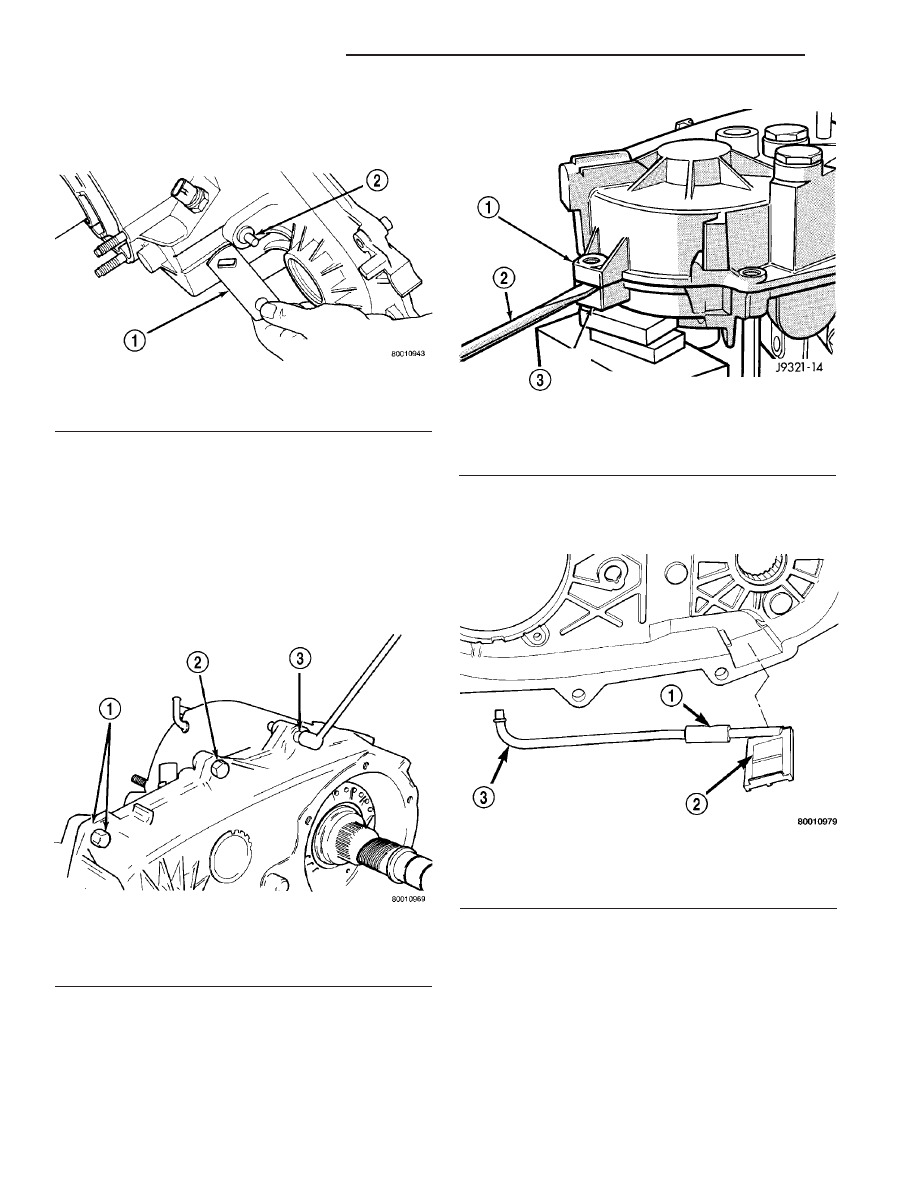
(5) Remove oil pickup tube from rear case (Fig.

14).

Fig. 14 Oil Pickup Tube Removal

1 - CONNECTING HOSE
2 - PICKUP SCREEN
3 - PICKUP TUBE

Fig. 11 Range Lever Removal

1 - RANGE LEVER
2 - SECTOR SHAFT

Fig. 12 Rear Case Alignment Bolt Locations

1 - DOWEL BOLT AND WASHER (2)
2 - CASE BOLT (5)
3 - SPLINE HEAD BOLT (1)

Fig. 13 Loosening Rear Case - Typical

1 - REAR CASE
2 - PRY TOOL (IN CASE SLOT)
3 - FRONT CASE

21 - 170

TRANSFER CASE - NV231

TJ

TRANSFER CASE - NV231 (Continued)

(6) Remove mode fork spring (Fig. 15).
(7) Pull front output shaft upward and out of front

output shaft bearing (Fig. 16).

(8) Remove front output shaft and chain.

SHIFT FORKS AND MAINSHAFT

(1) Remove detent plug, O-ring, detent spring and

detent plunger (Fig. 17).

(2) Remove mainshaft from mode sleeve and input

gear pilot bearing.

(3) Remove mode fork and sleeve as an assembly

(Fig. 18). Note position of sleeve for assembly refer-
ence. The short side of the sleeve faces upward.

Fig. 18 Mode Fork And Sleeve Removal

1 - MODE SLEEVE
2 - MODE FORK AND RAIL

Fig. 15 Mode Fork Spring Removal

1 - MODE SPRING

Fig. 16 Remove Front Output Shaft And Chain

1 - DRIVE CHAIN
2 - FRONT OUTPUT SHAFT
3 - SHAFT FRONT BEARING

Fig. 17 Detent Plug, Spring And Plunger Removal

1 - POPPET
2 - SPRING
3 - SCREW
4 - POPPET BORE (IN CASE)

TJ

TRANSFER CASE - NV231

21 - 171

TRANSFER CASE - NV231 (Continued)

(4) Remove range fork and hub as an assembly

(Fig. 19). Note fork position for installation reference.

(5) Remove shift sector from front case (Fig. 20).
(6) Remove shift sector bushing and O-ring (Fig.

21).

MAINSHAFT

(1) Remove mode hub retaining ring with heavy

duty snap-ring pliers (Fig. 22).

(2) Slide mode hub off mainshaft (Fig. 23).

Fig. 21 Sector Bushing And O-Ring Removal

1 - SEAL RETAINER
2 - SECTOR SHAFT BORE
3 - O-RING SEAL

Fig. 22 Mode Hub Retaining Ring Removal

1 - MODE HUB
2 - SNAP-RING PLIERS (HEAVY DUTY)
3 - MODE HUB RETAINING RING

Fig. 23 Mode Hub Removal

1 - MAINSHAFT
2 - MODE HUB

Fig. 19 Range Fork And Sleeve Removal

1 - RANGE HUB
2 - RANGE FORK

Fig. 20 Shift Sector Removal

1 - SHIFT SECTOR

21 - 172

TRANSFER CASE - NV231

TJ

TRANSFER CASE - NV231 (Continued)

(3) Slide drive sprocket off mainshaft (Fig. 24).

INPUT GEAR AND LOW RANGE GEAR

(1) Remove front bearing retainer attaching bolts

(Fig. 25).

(2) Remove front bearing retainer. Pry retainer

loose with pry tool positioned in slots at each end of
retainer (Fig. 26).

(3) Remove front bearing retainer seal. Tap seal

out with drift and hammer.

(4) Remove input gear retaining ring with heavy

duty snap-ring pliers (Fig. 27)

Fig. 24 Drive Sprocket Removal

1 - DRIVE SPROCKET
2 - MAINSHAFT

Fig. 25 Front Bearing Retainer Bolts

1 - FRONT CASE
2 - FRONT BEARING RETAINER
3 - RETAINER BOLTS

Fig. 26 Front Bearing Retainer Removal

1 - FRONT BEARING RETAINER
2 - RETAINER SLOT

Fig. 27 Removing Input Gear Retaining Ring

1 - INPUT GEAR BEARING RETAINING RING
2 - INPUT GEAR BEARING
3 - SNAP-RING PLIERS

TJ

TRANSFER CASE - NV231

21 - 173

TRANSFER CASE - NV231 (Continued)


Content   ..  518  519  520  521   ..