Jeep Wrangler TJ. Manual - part 432


  Index      Jeep     Jeep Wrangler TJ - service repair manual 2005 year


Search            


Content   ..  430  431  432  433   ..


Jeep Wrangler TJ. Manual - part 432


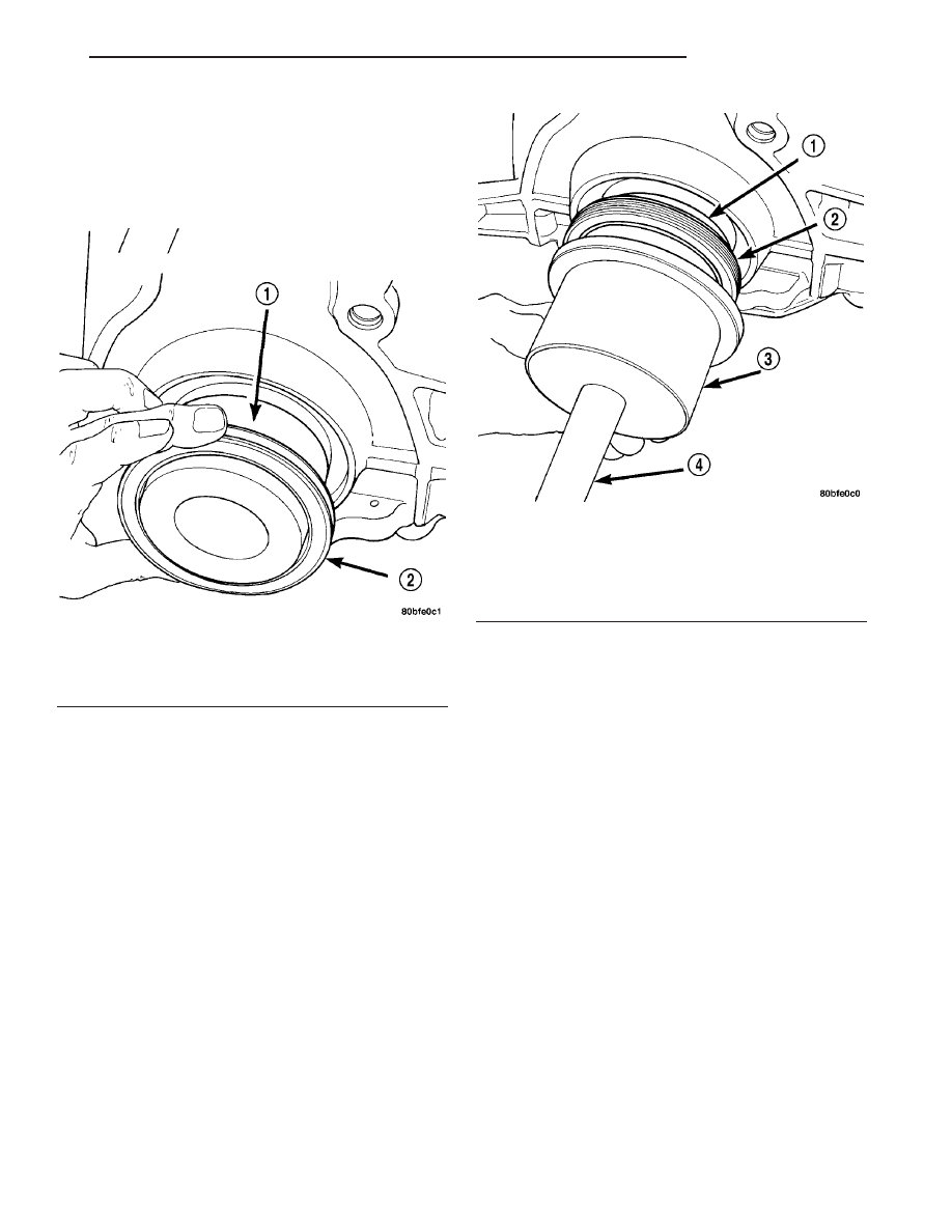
CAUTION: If the seal is driven into the block past
flush, this may cause an oil leak.

(4) Drive the seal into the block using Special Tool

6926-2 and handle C-4171 (Fig. 62) until the tool bot-
toms out against the block (Fig. 63).

(5) Install flex plate. Apply Mopar

t Lock & Seal

Adhesive to bolt threads and tighten bolts to 95 N·m
(70 ft. lbs.).

(6) Install the transmission.

PISTON & CONNECTING ROD

DESCRIPTION

The pistons are made of a cast aluminum alloy.

The pistons have pressed-in pins attached to forged
powdered metal connecting rods. The pistons pin is
offset 1 mm (0.0394 in.) towards the thrust side of
the piston. The connecting rods are a cracked cap
design and are not repairable. Hex head cap screws
are used to provide alignment and durability in the
assembly. The pistons and connecting rods are ser-
viced as an assembly.

OPERATION

The piston and connecting rod is the link between

the combustion force to the crankshaft.

REMOVAL

NOTE: Cylinder Head must be removed before Pis-
tons and Rods. Refer to Cylinder Head Removal in
this section.

(1) Remove top ridge of cylinder bores with a reli-

able ridge reamer before removing pistons from cyl-
inder block. Be sure to keep tops of pistons
covered during this operation
. Mark piston with
matching cylinder number (Fig. 64).

(2) Remove oil pan. Scribe the cylinder number on

the side of the rod and cap (Fig. 65) for identification.

(3) Pistons have a directional stamping in the

front half of the piston facing towards the front of
engine.

(4) Pistons and connecting rods must be removed

from top of cylinder block. Rotate crankshaft so that
each connecting rod is centered in cylinder bore.

(5) Remove Balance Shaft Assembly. Refer to Bal-

ance Shaft Removal in this section.

(6) Remove connecting rod cap bolts. Push each

piston and rod assembly out of cylinder bore.

NOTE: Be careful not to nick crankshaft journals.

(7) After removal, install bearing cap on the mat-

ing rod.

(8) Piston and Rods are serviced as an assembly.

Fig. 61 Rear Crankshaft Seal and Special Tool

6926-1

1 - SPECIAL TOOL 6926–1 PILOT
2 - SEAL

Fig. 62 Crankshaft Seal and Special Tools 6926-2 &

C-4171

1 - SPECIAL TOOL 6926–1 PILOT
2 - SEAL
3 - SPECIAL TOOL 6926–2 INSTALLER
4 - SPECIAL TOOL C-4171

TJ

ENGINE 2.4L

9 - 43

CRANKSHAFT OIL SEAL - REAR (Continued)

INSTALLATION

(1) Before installing pistons and connecting rod

assemblies into the bore, be sure that compression
ring gaps are staggered so that neither is in line with
oil ring rail gap.

(2) Before installing the ring compressor, make

sure the oil ring expander ends are butted and the
rail gaps located as shown in (Fig. 66). As viewed
from top.

(3) Immerse the piston head and rings in clean

engine oil, slide the ring compressor, over the piston
(Fig. 67). Be sure position of rings does not
change during this operation 
.

(4) The directional stamp on the piston should face

toward the front of the engine.

Fig. 63 Rear Crankshaft Seal - Installation

1 - SPECIAL TOOL 6926–2 INSTALLER

Fig. 64 Piston Markings

1 - DIRECTIONAL ARROW WILL BE IMPRINTED IN THIS AREA

Fig. 65 Identify Connecting Rod to Cylinder

Fig. 66 Piston Ring End Gap Position

1 - GAP OF LOWER SIDE RAIL
2 - NO. 1 RING GAP
3 - GAP OF UPPER SIDE RAIL
4 - NO. 2 RING GAP AND SPACER EXPANDER GAP

Fig. 67 Piston - Installation

9 - 44

ENGINE 2.4L

TJ

PISTON & CONNECTING ROD (Continued)

(5) Rotate crankshaft so that the connecting rod

journal is on the center of the cylinder bore. Insert
rod and piston assembly into cylinder bore and guide
rod over the crankshaft journal.

(6) Tap the piston down in cylinder bore, using a

hammer handle. At the same time, guide connecting
rod into position on connecting rod journal.

NOTE: The connecting rod cap bolts should not be
reused.

(7) Before installing the NEW bolts the threads

should be coated with clean engine oil.

(8) Install each bolt finger tight than alternately

torque each bolt to assemble the cap properly.

CAUTION: Do not use a torque wrench for second
part of last step.

(9) Tighten the bolts to 54 N·m PLUS 1/4 turn (40

ft. lbs. PLUS 1/4 turn).

(10) Using a feeler gauge, check connecting rod

side clearance (Fig. 68).

PISTON RINGS

STANDARD PROCEDURE

PISTON RING - FITTING

(1) Wipe cylinder bore clean. Insert ring and push

down with piston to ensure it is square in bore. The

ring gap measurement must be made with the ring
positioning at least 12 mm (0.50 inch) from bottom of
cylinder bore. Check gap with feeler gauge (Fig. 69).
Refer to Engine Specifications.

(2) Check piston ring to groove side clearance (Fig.

70). Refer to Engine Specifications.

Fig. 68 Checking Connecting Rod Side Clearance

Fig. 69 Piston Ring Gap

1 - FEELER GAUGE

Fig. 70 Piston Ring Side Clearance

1 - FEELER GAUGE

TJ

ENGINE 2.4L

9 - 45

PISTON & CONNECTING ROD (Continued)

PISTON RINGS - INSTALLATION

(1) Install rings with manufacturers I.D. mark fac-

ing up, to the top of the piston (Fig. 71).

CAUTION: Install piston rings in the following
order:

a. Oil ring expander.
b. Upper oil ring side rail.
c. Lower oil ring side rail.
d. No. 2 Intermediate piston ring.
e. No. 1 Upper piston ring.
(2)

Install the side rail by placing one end

between the piston ring groove and the expander.
Hold end firmly and press down the portion to be
installed until side rail is in position. Do not use a
piston ring expander 
(Fig. 72).

(3) Install upper side rail first and then the lower

side rail.

(4) Install No. 2 piston ring and then No. 1 piston

ring.

(5) Position piston ring end gaps as shown in (Fig.

73).

(6)

Position oil ring expander gap at least 45°

from the side rail gaps but not on the piston pin cen-
ter or on the thrust direction. Staggering ring gap is
important for oil control.

Fig. 71 Piston Ring Installation

1 - NO. 1 PISTON RING
2 - NO. 2 PISTON RING
3 - SIDE RAIL
4 - OIL RING
5 - SPACER EXPANDER

Fig. 72 Installing Side Rail - Typical

1 - SIDE RAIL END

Fig. 73 Piston

1 - GAP OF LOWER SIDE RAIL
2 - NO. 1 RING GAP
3 - GAP OF UPPER SIDE RAIL
4 - NO. 2 RING GAP AND SPACER EXPANDER GAP

9 - 46

ENGINE 2.4L

TJ

PISTON RINGS (Continued)


Content   ..  430  431  432  433   ..