Jeep Wrangler TJ. Manual - part 323


  Index      Jeep     Jeep Wrangler TJ - service repair manual 2005 year


Search            


Content   ..  321  322  323  324   ..


Jeep Wrangler TJ. Manual - part 323


WARNING:

TO

AVOID

PERSONAL

INJURY

OR

DEATH, ON VEHICLES EQUIPPED WITH AIRBAGS,
DISABLE THE SUPPLEMENTAL RESTRAINT SYS-
TEM

BEFORE

ATTEMPTING

ANY

STEERING

WHEEL, STEERING COLUMN, AIRBAG, OR INSTRU-
MENT PANEL COMPONENT DIAGNOSIS OR SER-
VICE. DISCONNECT AND ISOLATE THE BATTERY
NEGATIVE (GROUND) CABLE, THEN WAIT TWO
MINUTES FOR THE SYSTEM CAPACITOR TO DIS-
CHARGE BEFORE PERFORMING FURTHER DIAG-
NOSIS OR SERVICE. THIS IS THE ONLY SURE WAY
TO DISABLE THE SUPPLEMENTAL RESTRAINT
SYSTEM. FAILURE TO TAKE THE PROPER PRE-
CAUTIONS COULD RESULT IN ACCIDENTAL AIR-
BAG DEPLOYMENT.

NOTE: Before starting this procedure, be certain to
turn the steering wheel until the front wheels are in
the straight-ahead position.

(1) Place the front wheels in the straight ahead

position.

(2) Remove the driver airbag from the steering

wheel. (Refer to 8 - ELECTRICAL/RESTRAINTS/
DRIVER AIRBAG - REMOVAL).

(3) Disconnect the two upper clockspring pigtail

wire connectors from the two speed control switches
or the two trim bezels located within the two spoke
cavities of the steering wheel.

CAUTION: Be certain that the screws that secure
the steering wheel puller to the steering wheel are
fully engaged in the steering wheel armature with-
out passing through the steering wheel and damag-
ing the clockspring.

(4) Remove the steering wheel from the steering

column. (Refer to 19 - STEERING/COLUMN/STEER-
ING WHEEL - REMOVAL).

(5) Remove the steering column opening cover

from the instrument panel. (Refer to 23 - BODY/IN-
STRUMENT PANEL/STEERING COLUMN OPEN-
ING COVER - REMOVAL).

(6) From below the steering column, remove the

two screws that secure the lower steering column
shroud to the upper shroud (Fig. 18).

(7) If the vehicle is equipped with the optional tilt

steering column, move the tilt steering column to the
fully lowered position and leave the tilt release lever
in the released (down) position.

(8) Using hand pressure, push gently inward on

both sides of the upper shroud near the parting line
between the upper and lower shrouds to release the
snap features that secure it to the lower shroud.

(9) Remove both the upper and lower shrouds from

the steering column.

(10) Disconnect the two body wire harness connec-

tors for the clockspring from the two connector recep-
tacles below the steering column on the back of the
clockspring housing (Fig. 19).

(11) Using a small screwdriver, gently pry both

plastic latches that secure the clockspring away from
the steering column upper housing far enough to pull
the clockspring away from the upper housing.

NOTE: If the clockspring plastic latches are broken,
be certain to remove the broken pieces from the
steering column upper housing.

(12) Remove the clockspring from the steering col-

umn upper housing. The clockspring cannot be
repaired. It must be replaced if faulty or damaged, or
if the driver airbag has been deployed.

(13) If the removed clockspring is to be reused, be

certain to secure the clockspring rotor to the clock-
spring case to maintain clockspring centering until it
is reinstalled on the steering column. If clockspring
centering is not maintained, the clockspring must be
centered again before it is reinstalled. (Refer to 8 -
ELECTRICAL/RESTRAINTS/CLOCKSPRING

-

STANDARD PROCEDURE - CLOCKSPRING CEN-
TERING).

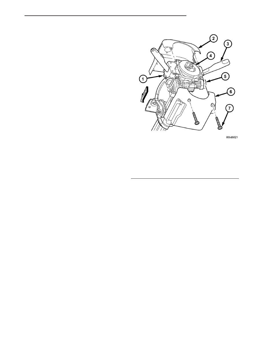
Fig. 18 Steering Column Shrouds Remove/Install

1 - LEFT MULTI-FUNCTION SWITCH
2 - UPPER SHROUD
3 - RIGHT MULTI-FUNCTION SWITCH
4 - CLOCKSPRING
5 - IGNITION LOCK CYLINDER HOUSING
6 - LOWER SHROUD
7 - SCREW (2)

TJ

RESTRAINTS

8O - 17

CLOCKSPRING (Continued)

INSTALLATION

The clockspring cannot be repaired. It must be

replaced if faulty or damaged, or if the driver airbag
has been deployed.

If the clockspring is not properly centered in rela-

tion to the steering wheel, steering shaft and steer-
ing

gear,

it

may

be

damaged.

(Refer

to

8

-

ELECTRICAL/RESTRAINTS/CLOCKSPRING

-

STANDARD PROCEDURE - CLOCKSPRING CEN-
TERING).

Service

replacement

clocksprings

are

shipped pre-centered and with a plastic locking pin
installed. This locking pin should not be removed
until the clockspring has been installed on the steer-
ing column. If the locking pin is removed before the
clockspring is installed on a steering column, the
clockspring centering procedure must be performed.

WARNING:

TO

AVOID

PERSONAL

INJURY

OR

DEATH, ON VEHICLES EQUIPPED WITH AIRBAGS,
DISABLE THE SUPPLEMENTAL RESTRAINT SYS-
TEM

BEFORE

ATTEMPTING

ANY

STEERING

WHEEL, STEERING COLUMN, AIRBAG, OR INSTRU-
MENT PANEL COMPONENT DIAGNOSIS OR SER-
VICE. DISCONNECT AND ISOLATE THE BATTERY
NEGATIVE (GROUND) CABLE, THEN WAIT TWO
MINUTES FOR THE SYSTEM CAPACITOR TO DIS-
CHARGE BEFORE PERFORMING FURTHER DIAG-
NOSIS OR SERVICE. THIS IS THE ONLY SURE WAY
TO DISABLE THE SUPPLEMENTAL RESTRAINT
SYSTEM. FAILURE TO TAKE THE PROPER PRE-
CAUTIONS COULD RESULT IN ACCIDENTAL AIR-
BAG DEPLOYMENT.

NOTE: Before starting this procedure, be certain
that the front wheels are still in the straight-ahead
position.

(1) Be certain that the left multi-function switch

control stalk is in the neutral position, then carefully
slide the centered clockspring down over the steering
column upper shaft until both the upper and lower
clockspring latches engage the steering column upper
housing (Fig. 19).

(2) Reconnect the two body wire harness connec-

tors for the clockspring to the two connector recepta-
cles below the steering column on the back of the
clockspring housing.

(3) Position both the upper and lower shrouds onto

the steering column (Fig. 18). Be certain that the
locating tabs for the left and right multi-function
switch

control

stalk

watershields

are

properly

engaged in the openings of both the upper and lower
shrouds.

(4) Align the snap features on the upper shroud

with the receptacles on the lower shroud and apply
hand pressure to snap them together.

(5) From below the steering column, install and

tighten the two screws that secure the lower steering
column shroud to the upper shroud. Tighten the
screws to 2 N·m (18 in. lbs.).

(6) If the vehicle is equipped with the optional tilt

steering column, move the tilt steering column to the
fully raised position and secure it in place by moving
the tilt release lever back to the locked (up) position.

(7) Reinstall the steering column opening cover

onto the instrument panel. (Refer to 23 - BODY/IN-
STRUMENT PANEL/STEERING COLUMN OPEN-
ING COVER - INSTALLATION).

(8) If a new clockspring has been installed, remove

the locking pin that is securing the clockspring rotor
to the clockspring case to maintain clockspring cen-
tering.

(9) Reinstall the steering wheel onto the steering

column. (Refer to 19 - STEERING/COLUMN/STEER-
ING WHEEL - INSTALLATION).

(10) Reconnect the two upper clockspring pigtail

wire connectors to the two speed control switches or
the two trim bezels located within the two spoke cav-
ities of the steering wheel.

(11) Reinstall the driver airbag onto the steering

wheel. (Refer to 8 - ELECTRICAL/RESTRAINTS/
DRIVER AIRBAG - INSTALLATION).

Fig. 19 Clockspring Remove/Install - Typical

1 - CLOCKSPRING
2 - LATCHES
3 - BODY WIRE HARNESS
4 - LEFT MULTI-FUNCTION SWITCH
5 - SWITCH HOUSING
6 - STEERING COLUMN
7 - RIGHT MULTI-FUNCTION SWITCH

8O - 18

RESTRAINTS

TJ

CLOCKSPRING (Continued)

DRIVER AIRBAG

DESCRIPTION

The color-keyed, injection molded, thermoplastic

driver airbag protective trim cover is the most visible
part of the driver airbag (Fig. 20). The driver airbag
is located in the center of the steering wheel, where
it is secured with two screws to the two horizontal
spokes of the four-spoke steering wheel armature. All
models have a Jeep logo embossed in the center of
the trim cover. Concealed beneath the driver airbag
trim cover are the horn switch, the folded airbag
cushion, the airbag cushion retainer, the airbag hous-
ing, the airbag inflator, and the retainers that secure
the inflator to the airbag housing.

The airbag cushion, housing, and inflator unit is

secured within an integral receptacle on the back of
the trim cover (Fig. 21). The driver airbag trim cover
has locking blocks molded into the back side of it
that engage a lip formed around the perimeter of the
airbag housing. Two stamped metal retainers then fit
over the inflator mounting studs on the back of the
airbag housing and tabs on the retainers are engaged
in slots within the upper and lower trim cover lock-
ing blocks, securely locking the cover into place. The
stamped metal retainers are secured to the four air-
bag inflator mounting studs with nuts.

The

resistive

membrane-type

horn

switch

is

secured within a plastic tray that is inserted into a
pocket or pouch sewn onto the airbag cushion
retainer strap, between the trim cover and the folded
airbag cushion. The horn switch ground pigtail wire
has an eyelet terminal connector that is captured on
the upper right inflator mounting stud between the
inflator and the upper trim cover retainer. The horn
switch feed pigtail wire has a white, molded plastic

insulator that is secured by an integral retainer to a
mounting hole located in the upper trim cover
retainer near the upper left corner on the back of the
airbag housing, and is connected to the vehicle elec-
trical system through a dedicated pigtail wire and
connector from the clockspring.

The airbag used in this model is a Next Genera-

tion-type that complies with revised federal airbag
standards to deploy with less force than those used
in some prior models. A radial deploying fabric cush-
ion with internal tethers is used. The airbag inflator
is a conventional pyrotechnic-type unit that is
secured by four hex nuts to four studs that extend
through the back of the stamped metal airbag hous-
ing from the airbag cushion retainer ring. A keyed
connector receptacle on the driver airbag inflator con-
nects the inflator initiator to the vehicle electrical
system through a yellow-jacketed, two-wire pigtail
harness of the clockspring. The driver airbag cannot
be repaired, and must be replaced if deployed or in
any way damaged. The driver airbag trim cover and
the horn switch are available individually, and may
be disassembled from the driver airbag for service
replacement.

OPERATION

The driver airbag is deployed by electrical signals

generated by the Airbag Control Module (ACM)
through the driver airbag squib circuit to the initia-
tor in the airbag inflator. When the ACM sends the

Fig. 20 Driver Airbag Trim Cover

1 - STEERING WHEEL
2 - TRIM COVER

Fig. 21 Driver Airbag Trim Cover

1 - UPPER RETAINER
2 - AIRBAG HOUSING
3 - TRIM COVER
4 - NUT (4)
5 - LOWER RETAINER
6 - INFLATOR
7 - STUD (4)

TJ

RESTRAINTS

8O - 19

proper electrical signal to the initiator the electrical
energy generates enough heat to initiate a small
pyrotechnic charge which, in turn ignites chemical
pellets within the inflator. Once ignited, these chem-
ical pellets burn rapidly and produce a large quantity
of inert gas. The inflator is sealed to the back of the
airbag housing and a diffuser in the inflator directs
all of the inert gas into the airbag cushion, causing
the cushion to inflate. As the cushion inflates, the
driver airbag trim cover will split at predetermined
breakout lines, then fold back out of the way along
with the horn switch unit. Following an airbag
deployment, the airbag cushion quickly deflates by
venting the inert gas towards the instrument panel
through the porous fabric material used to construct
the back (steering wheel side) panel of the airbag
cushion.

Some of the chemicals used to create the inert gas

may be considered hazardous while in their solid
state before they are burned, but they are securely
sealed within the airbag inflator. Typically, all poten-
tially hazardous chemicals are burned during an air-
bag deployment event. The inert gas that is produced
when the chemicals are burned is harmless. How-
ever, a small amount of residue from the burned
chemicals may cause some temporary discomfort if it
contacts the skin, eyes, or breathing passages. If skin
or eye irritation is noted, rinse the affected area with
plenty of cool, clean water. If breathing passages are
irritated, move to another area where there is plenty
of clean, fresh air to breath. If the irritation is not
alleviated by these actions, contact a physician.

REMOVAL

The following procedure is for replacement of a

faulty or damaged driver airbag. If the airbag is
faulty or damaged, but not deployed, review the rec-
ommended procedures for handling non-deployed
supplemental restraints. (Refer to 8 - ELECTRICAL/
RESTRAINTS - STANDARD PROCEDURE - HAN-
DLING

NON-DEPLOYED

SUPPLEMENTAL

RESTRAINTS).

If

the

driver

airbag

has

been

deployed, review the recommended procedures for
service after a supplemental restraint deployment
before removing the airbag from the vehicle. (Refer to
8 - ELECTRICAL/RESTRAINTS - STANDARD PRO-
CEDURE - SERVICE AFTER A SUPPLEMENTAL
RESTRAINT DEPLOYMENT).

WARNING:

TO

AVOID

PERSONAL

INJURY

OR

DEATH, ON VEHICLES EQUIPPED WITH AIRBAGS,
DISABLE THE SUPPLEMENTAL RESTRAINT SYS-
TEM

BEFORE

ATTEMPTING

ANY

STEERING

WHEEL, STEERING COLUMN, AIRBAG, OR INSTRU-
MENT PANEL COMPONENT DIAGNOSIS OR SER-
VICE. DISCONNECT AND ISOLATE THE BATTERY

NEGATIVE (GROUND) CABLE, THEN WAIT TWO
MINUTES FOR THE SYSTEM CAPACITOR TO DIS-
CHARGE BEFORE PERFORMING FURTHER DIAG-
NOSIS OR SERVICE. THIS IS THE ONLY SURE WAY
TO DISABLE THE SUPPLEMENTAL RESTRAINT
SYSTEM. FAILURE TO TAKE THE PROPER PRE-
CAUTIONS COULD RESULT IN ACCIDENTAL AIR-
BAG DEPLOYMENT.

WARNING:

TO

AVOID

PERSONAL

INJURY

OR

DEATH, WHEN REMOVING A DEPLOYED AIRBAG,
RUBBER

GLOVES,

EYE

PROTECTION,

AND

A

LONG-SLEEVED SHIRT SHOULD BE WORN. THERE
MAY BE DEPOSITS ON THE AIRBAG CUSHION AND
OTHER INTERIOR SURFACES. IN LARGE DOSES,
THESE DEPOSITS MAY CAUSE IRRITATION TO THE
SKIN AND EYES.

(1) Disconnect and isolate the battery negative

cable. Wait two minutes for the system capacitor to
discharge before further service.

(2) From the underside of the steering wheel,

remove the two screws that secure the driver airbag
to the steering wheel armature (Fig. 22).

(3) Pull the driver airbag away from the steering

wheel far enough to access the two electrical connec-
tions at the back of the airbag housing.

(4) Disconnect the clockspring pigtail wire connec-

tor for the horn switch from the horn switch feed pig-
tail wire connector located on the back of the driver
airbag.

Fig. 22 Driver Airbag Remove/Install

1 - STEERING WHEEL
2 - CLOCKSPRING PIGTAIL WIRE (HORN SWITCH)
3 - DRIVER AIRBAG
4 - CLOCKSPRING PIGTAIL WIRE (AIRBAG)
5 - SCREW (2)

8O - 20

RESTRAINTS

TJ

DRIVER AIRBAG (Continued)


Content   ..  321  322  323  324   ..