Jeep Wrangler TJ. Manual - part 316


  Index      Jeep     Jeep Wrangler TJ - service repair manual 2005 year


Search            


Content   ..  314  315  316  317   ..


Jeep Wrangler TJ. Manual - part 316


SIDE REPEATER LAMP CONDITION CHART

CONDITION

POSSIBLE CAUSES

CORRECTION

TURN SIGNALS OPERATE

NORMALLY, ONE REPEATER

LAMP DOES NOT

ILLUMINATE

1. Inoperative, damaged or burned out
lamp.

4. Replace the lamp.

2. Poor electrical connection at lamp.

2. Check for proper wire harness
connection and circuit terminal
tension at the lamp.

3. Open or high resistance in the voltage
circuit to the inoperative lamp.

3. Repair the open or high
resistance in the repeater lamp
voltage circuit.

4. Open, high resistance in the ground
circuit to the inoperative lamp.

4. Repair the open, high resistance
in the repeater lamp ground circuit.

TAIL LAMP UNIT

DESCRIPTION

Each tail lamp assembly contains a lens, housing

and two lamps. One lamp has two filaments and is
used for tail, stop, turn signal, rear side marker and
license plate (left side only) lamp functions. The
other lamp has a single filament and is used for
back-up light illumination.

OPERATION

Each tail lamp assembly can be serviced sepa-

rately. Each lamp can also be serviced separately.
The headlamp switch controls tail lamp operation.
The multi-function switch controls turn signal opera-
tion. The back-up light switch controls back-up light
operation. The brake lamp switch controls stop lamp
operation.

REMOVAL

(1) Disconnect and isolate the negative battery

cable.

(2) From the underside of the vehicle, remove the

push-in fastener that secures the bottom rear edge of
the rear wheelhouse splash shield to the body.

(3) Pull the rear of the wheelhouse splash shield

away from the body and reach upward to disconnect
the wire harness connector from the tail lamp.

(4) Remove the screws that secure the tail lamp

lens to the tail lamp housing (Fig. 30).

(5) Remove the tail lamp lens and gasket from the

tail lamp housing.

(6) Remove the bolts that secure the tail lamp

housing to the body.

(7) Remove the tail lamp housing from the body.

INSTALLATION

(1) Position the tail lamp housing to the body.

(2) Install the bolts that secure the tail lamp hous-

ing to the body. Tighten the bolts securely.

NOTE: Install the tail lamp lens with the clear por-
tion (back-up lens) at the top of the housing. Make
sure that the gasket is correctly in place and not
twisted or torn.

(3) Install the tail lamp lens and gasket onto the

tail lamp housing.

NOTE: Do not overtighten the screws or damage to
the tail lamp lens may result.

(4) Install the screws that secure the tail lamp

lens to the tail lamp housing. Tighten the screws
securely.

(5) Connect the wire harness connector to the tail

lamp.

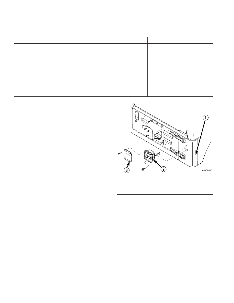
Fig. 30 Tail Lamp Housing

1 - BODY
2 - TAIL LAMP HOUSING
3 - TAIL LAMP LENS

TJ

LAMPS/LIGHTING - EXTERIOR

8L - 29

REPEATER LAMP (Continued)

(6) Install the push-in fastener that secures the

bottom rear edge of the rear wheelhouse splash
shield to the body.

(7) Reconnect the negative battery cable.

TAIL LAMP

REMOVAL

(1) Disconnect and isolate the negative battery

cable.

(2) Remove the screws that secure the tail lamp

lens to the tail lamp housing (Fig. 31).

(3) Remove the tail lamp lens and gasket from the

tail lamp housing.

(4) Push and rotate the lamp(s) one-third turn

counterclockwise, then pull the lamp straight out of
the socket

INSTALLATION

(1) Install the lamp(s) by pushing the lamp into

the tail lamp socket and turning it one-third clock-
wise.

NOTE: Install the tail lamp lens with the clear por-
tion (back-up lens) at the top of the housing. Make
sure that the gasket is correctly in place and not
twisted or torn.

(2) Install the tail lamp lens and gasket onto the

tail lamp housing.

NOTE: Do not overtighten the screws or damage to
the tail lamp lens may result.

(3) Install the screws that secure the tail lamp

lens to the tail lamp housing. Tighten the screws
securely.

(4) Reconnect the negative battery cable.

TURN SIGNAL CANCEL CAM

DESCRIPTION

The turn signal cancel cam consists of two lobes

that are integral to the lower surface of the clock-
spring rotor. The clockspring mechanism provides
turn signal cancellation as well as a constant electri-
cal connection between the driver airbag, steering
wheel accessories and the cross body wire harness on
the steering column. The housing of the clockspring
is secured to the steering column and remains sta-
tionary. The rotor of the clockspring, including the
turn signal cancel cam lobes rotate with the steering
wheel.

The turn signal cancel cam is integral to the clock-

spring and cannot be repaired. If faulty or damaged,
the entire clockspring assembly must be replaced.
(Refer to 8 - ELECTRICAL/RESTRAINTS/CLOCK-
SPRING - REMOVAL).

OPERATION

The turn signal cancel cam has two lobes molded

into the lower surface of the clockspring rotor. When
the turn signals are activated by moving the left
multi-function switch control stalk to a detent posi-
tion, a turn signal cancel actuator is extended from
the inside surface of the left multi-function switch
housing toward the clockspring rotor. When the
steering wheel is rotated during the turn, one of the
two turn signal cancel cam lobes will contact the
turn signal cancel actuator, but the cancel actuator
stays latched. When the steering wheel is rotated
back to center as the turn is completed, the cancel
actuator is unlatched and releases the left multi-
function switch control stalk from its detent, cancel-
ling the turn signal event.

Fig. 31 Tail Lamp Lens

8L - 30

LAMPS/LIGHTING - EXTERIOR

TJ

TAIL LAMP UNIT (Continued)

UNDERHOOD LAMP UNIT

REMOVAL

(1) Disconnect and isolate the negative battery

cable.

(2) Disconnect the wire harness connector from the

underhood lamp (Fig. 32).

(3) Remove the screw that secures the underhood

lamp to the inner hood panel.

(4) Remove the underhood lamp from the vehicle.

INSTALLATION

(1) Position the underhood lamp onto the inner

hood panel.

(2) Install the screw that secures the underhood

lamp to the inner hood panel. Tighten the screw
securely.

(3) Connect the wire harness connector to the

underhood lamp.

(4) Reconnect the negative battery cable.

UNDERHOOD LAMP

REMOVAL

(1) Disconnect and isolate the negative battery

cable.

(2) Insert a small flat blade in the access slot

between the lamp housing and lamp lens.

(3) Pry the lamp lens upward and remove the

lamp lens.

(4) Press the lamp terminal inward (Fig. 33) to

release the lamp.

INSTALLATION

(1) Engage the lamp wire loop to the terminal clos-

est to the lamp housing wire connector.

(2) Press the opposite terminal inward and engage

the remaining lamp wire loop onto the terminal.

(3) Position the lamp lens onto the lamp housing

and press the lens into place.

(4) Reconnect the negative battery cable.

Fig. 32 Underhood Lamp

1 - UNDERHOOD LAMP
2 - HOOD

Fig. 33 Underhood Lamp

1 - LAMP
2 - LAMP TERMINAL
3 - LAMP WIRE LOOP
4 - LAMP HOUSING

TJ

LAMPS/LIGHTING - EXTERIOR

8L - 31

LAMPS/LIGHTING - INTERIOR

TABLE OF CONTENTS

page

page

LAMPS/LIGHTING - INTERIOR

SPECIFICATIONS

INTERIOR LAMPS

. . . . . . . . . . . . . . . . . . . . . 32

DOME LAMP UNIT

REMOVAL

. . . . . . . . . . . . . . . . . . . . . . . . . . . . . 32

INSTALLATION

. . . . . . . . . . . . . . . . . . . . . . . . . 32

DOME LAMP

REMOVAL

. . . . . . . . . . . . . . . . . . . . . . . . . . . . . 33

INSTALLATION

. . . . . . . . . . . . . . . . . . . . . . . . . 33

DOOR AJAR SWITCH

DESCRIPTION

. . . . . . . . . . . . . . . . . . . . . . . . . 33

OPERATION

. . . . . . . . . . . . . . . . . . . . . . . . . . . 34

DIAGNOSIS AND TESTING - DOOR AJAR

SWITCH

. . . . . . . . . . . . . . . . . . . . . . . . . . . . 34

REMOVAL

. . . . . . . . . . . . . . . . . . . . . . . . . . . . . 34

INSTALLATION

. . . . . . . . . . . . . . . . . . . . . . . . . 34

REAR WIPER/WASHER SWITCH

ILLUMINATION LAMP
REMOVAL

. . . . . . . . . . . . . . . . . . . . . . . . . . . . . 35

INSTALLATION

. . . . . . . . . . . . . . . . . . . . . . . . . 35

LAMPS/LIGHTING - INTERIOR

SPECIFICATIONS

INTERIOR LAMPS

CAUTION: Do not use bulbs that have a higher can-
dle power than the bulb listed in the Bulb Applica-
tion Table. Damage to lamp housing and lens can
result.

Some components have lamps that can only be ser-

viced by an Authorized Service Center (ASC) after
the component is removed from the vehicle.

The following table lists the various lamp trade

numbers or part numbers.

LAMP

BULB

Dome (Sound Bar)

912

Under Hood

561

Underpanel Courtesy

906

Instrument Cluster
Illumination

103

Instrument Cluster
Warning

74

Automatic Transmission
Indicator

658

DOME LAMP UNIT

REMOVAL

NOTE: The dome lamp removal procedure is the
same for both the right and left side dome lamps.

(1) Disconnect the negative battery cable.

NOTE: The dome lamp lens locating tab is larger
than the lens retaining tabs.

(2) Insert a small flat blade between the dome

lamp housing and dome lamp lens. Carefully pry the
lamp lens from the lamp housing (Fig. 1).

(3) Remove the screws that secure the dome lamp

housing to the speaker housing.

(4) Remove the dome lamp housing from the

speaker housing and disconnect the wire harness
connector from the dome lamp.

INSTALLATION

NOTE: The dome lamp installation procedure is the
same for both the right and left side dome lamps.

(1) Connect the wire harness connector to the

dome lamp.

NOTE: The dome lamp housing is equipped with a
locating tab that must be inserted into the slot in
the speaker housing.

(2) Align the locating tab with the slot and posi-

tion the dome lamp housing into the speaker housing
(Fig. 2).

8L - 32

LAMPS/LIGHTING - INTERIOR

TJ


Content   ..  314  315  316  317   ..