Jeep Wrangler TJ. Manual - part 290


  Index      Jeep     Jeep Wrangler TJ - service repair manual 2005 year


Search            


Content   ..  288  289  290  291   ..


Jeep Wrangler TJ. Manual - part 290


HEATED SYSTEMS

TABLE OF CONTENTS

page

page

HEATED GLASS . . . . . . . . . . . . . . . . . . . . . . . . . . . 1

HEATED MIRRORS . . . . . . . . . . . . . . . . . . . . . . . . . 7

HEATED GLASS

TABLE OF CONTENTS

page

page

HEATED GLASS

DESCRIPTION

. . . . . . . . . . . . . . . . . . . . . . . . . . 1

OPERATION

. . . . . . . . . . . . . . . . . . . . . . . . . . . . 1

DIAGNOSIS AND TESTING

ELECTRIC BACKLIGHT (EBL) SYSTEM

. . . . . 2

REAR WINDOW DEFOGGER RELAY

DESCRIPTION

. . . . . . . . . . . . . . . . . . . . . . . . . . 3

OPERATION

. . . . . . . . . . . . . . . . . . . . . . . . . . . . 3

REMOVAL

. . . . . . . . . . . . . . . . . . . . . . . . . . . . . 3

INSTALLATION

. . . . . . . . . . . . . . . . . . . . . . . . . . 4

REAR WINDOW DEFOGGER SWITCH

DESCRIPTION

. . . . . . . . . . . . . . . . . . . . . . . . . . 4

OPERATION

. . . . . . . . . . . . . . . . . . . . . . . . . . . . 4

DIAGNOSIS AND TESTING

REAR WINDOW DEFOGGER SWITCH

. . . . . . 5

REMOVAL

. . . . . . . . . . . . . . . . . . . . . . . . . . . . . 5

INSTALLATION

. . . . . . . . . . . . . . . . . . . . . . . . . . 5

REAR WINDOW DEFOGGER GRID

STANDARD PROCEDURE

GRID LINE AND TERMINAL REPAIR

. . . . . . . . 6

HEATED GLASS

DESCRIPTION

CAUTION: Grid lines can be damaged or scraped
off with sharp instruments. Care should be taken in
cleaning

glass

or

removing

foreign

materials,

decals or stickers. Normal glass cleaning solvents
or hot water used with rags or toweling is recom-
mended.

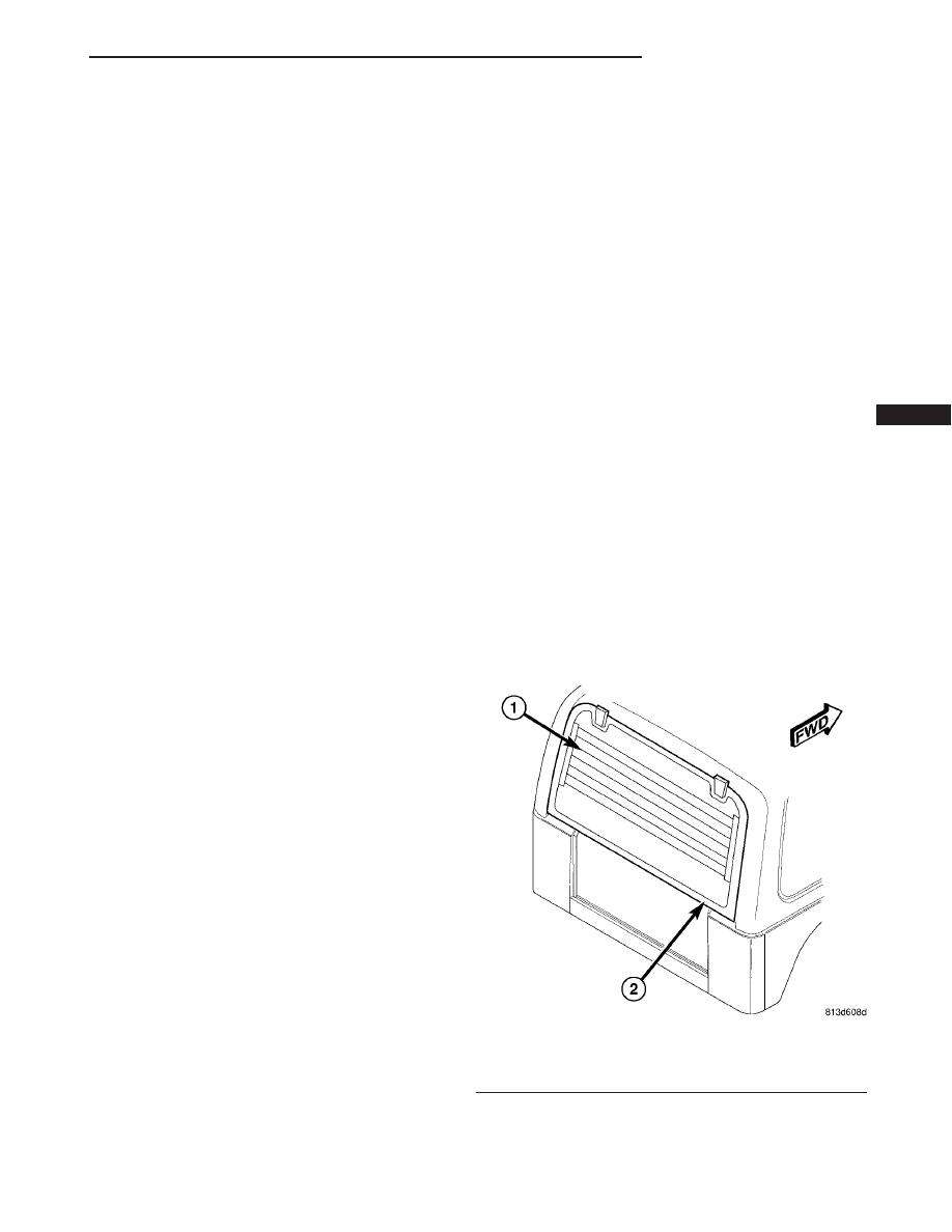
The rear window defogger system, also known as

electric backlight (EBL), consists of two vertical bus
bars linked by a series of grid lines fired onto the
inside surface of the rear window (Fig. 1).

The EBL system is turned On or Off by a control

switch mounted into the accessory switch bezel in the
instrument panel and the timer and logic circuitry in
the instrument cluster assembly (Refer to 8 - ELEC-
TRICAL/HEATED GLASS/REAR WINDOW DEFOG-
GER SWITCH - DESCRIPTION).

Circuit protection is provided by three cartridge

fuses located in the fuse block. One fuse for the con-
trol circuit, another for the heated grid circuit and
the third fuse for the rear window defogger indicator
lamp circuit.

OPERATION

The electric backlight (EBL) system is controlled

by a momentary switch located in the accessory

Fig. 1 Rear Window Defogger

1 - REAR DEFOGGER GRID
2 - REAR WINDOW

TJ

HEATED SYSTEMS

8G - 1

switch bezel on the instrument panel (Fig. 2). When
the rear window defogger switch is pressed to the On
position, the instrument cluster energizes the rear
window defogger (EBL) relay, which then directs
fused battery current through the relay and to the
rear defogger grid lines and the heated side view
mirrors, when equipped. The grid lines heat the glass
to help clear the rear window and side mirror sur-
faces of fog or frost.

An amber indicator in the rear window defogger

switch will illuminate to indicate when the EBL sys-
tem is turned on. The instrument cluster contains
the EBL system control circuitry including the timer
logic.

NOTE: The EBL system turns off automatically after
ten minutes of initial operation. Each following acti-
vation cycle of the EBL system will last five min-
utes.

The EBL system will be automatically turned off

after an initial programmed time interval of about
ten minutes. After the initial time interval has
expired, if the rear window defogger switch is turned
on again during the same ignition cycle, the EBL sys-
tem will automatically turn off after about five min-
utes. The EBL system will automatically shut off if
the ignition switch is turned to the Off position, or it
can be turned off manually by pressing the rear win-
dow defogger switch a second time.

Repair of the rear window defogger grid lines, bus

bars, terminals or pigtail wires can be accomplished
using the Mopar Rear Window Defogger Repair Kit
(Part Number 04549275) or equivalent (Refer to 8 -
ELECTRICAL/HEATED

GLASS/REAR

WINDOW

DEFOGGER GRID - STANDARD PROCEDURE -
GRID LINE AND TERMINAL REPAIR).

DIAGNOSIS AND TESTING

ELECTRIC BACKLIGHT (EBL) SYSTEM

NOTE: Illumination of the defogger switch indicator
lamp does not necessary mean that electrical cur-
rent is reaching the rear glass heating grid lines.

NOTE: For circuit descriptions and diagrams of the
rear window defogger (EBL) system, refer to 8W -
WIRING DIAGRAM INFORMATION.

Operation of the electric backlight (EBL) system

can be confirmed by the following:

(1) Use a DRBIII

t scan tool and check for diagnos-

tic trouble codes (DTCs) related to the instrument
cluster. If no DTCs are found, go to Step 2. If any

DTCs are found, repair as required, then proceed to
Step 2

(2) Turn the ignition switch to the On position. Set

the rear window defogger switch in the On position.
The rear window defogger operation can be checked
by feeling the surfaces of the rear window glass or
outside

heated

rear

view

mirror

glass,

when

equipped.

A

distinct

difference

in

temperature

between the grid lines and the adjacent clear glass or
the mirror glass should be detected within three to
four minutes of operation.

(3) If a temperature difference is not detected, use

a 12-volt DC voltmeter and contact the rear glass
heating grid power feed terminal A with the positive
lead, and terminal B with the negative lead (Fig. 3).
The voltmeter should read battery voltage. If the
voltmeter does not read battery voltage, check the
following:

• Confirm that the ignition switch is in the On

position.

• Make sure that the EBL feed wire and ground

wire are connected to the terminals. Confirm that the
ground wire has continuity to ground.

• Check the EBL relay located in the power distri-

bution center (PDC) in the engine compartment.
Check the fuses in the fuse block located in the pas-
senger compartment. The relay and fuses must be
tight in their receptacles and all electrical connec-
tions must be secure. Refer to the appropriate wiring
information for diagnosis and testing of the ISO-stan-
dard relay.

When the above steps have been completed and the

rear glass heating grid is still inoperative, one or
more of the following is faulty:

Fig. 2 03 ACCESSORY SWITCH BEZEL

1 - BEZEL SCREWS (4)
2 - BEZEL
3 - WIRE HARNESS
4 - ELECTRICAL CONNECTORS (7)

8G - 2

HEATED GLASS

TJ

HEATED GLASS (Continued)

• Rear window defogger switch in the instrument

panel.

• Rear window defogger relay control circuity in

the instrument cluster.

• Rear window defogger grid lines (all grid lines

would have to be broken, or the power feed or ground
wire disconnected, for the entire heated grid to be
inoperative).

(4) If the EBL system operation has been verified

but the rear window defogger indicator does not illu-
minate, check the indicator power feed fuse located
in the fuse block. If the fuse is Ok, replace the rear
window defogger switch (Refer to 8 - ELECTRICAL/
HEATED

GLASS/REAR

WINDOW

DEFOGGER

SWITCH - REMOVAL).

REAR WINDOW DEFOGGER
RELAY

DESCRIPTION

The rear window defogger (EBL) relay (Fig. 4) is a

International

Standards

Organization

(ISO)-type

relay. Relays conforming to the ISO specifications
have common physical dimensions, current capaci-
ties, terminal functions and patterns. The EBL relay
is a electromechanical device that switches battery
current through a fuse in the fuse block to the rear
window defogger grid and to the light-emitting diode
(LED) indicator of the rear window defogger switch
and also to the heating elements of the outside rear
view mirrors (when equipped). The EBL relay is
energized when the relay coil is provided a ground
path by the control circuitry within the instrument
cluster.

The EBL relay is located in the power distribution

center (PDC) in the engine compartment.

OPERATION

The ISO-standard rear window defogger (EBL)

relay is an electromechanical switch that uses a low
current input controlled by the body control module
(BCM) to control the high current output to the rear
window defogger grid lines The movable, common
feed relay contact is held against the fixed, normally
closed relay contact by spring pressure. When the
electromagnetic relay coil is energized, it draws the
movable common feed relay contact away from the
fixed, normally closed relay contact and, holds it
against the fixed, normally open relay contact. This
action allows high current to flow to the rear window
defogger grid lines.

When the relay coil is de-energized, spring pres-

sure returns the movable relay contact back against
the fixed, normally closed contact point. The resistor
or diode is connected in parallel with the relay coil,
and helps to dissipate voltage spikes and electromag-
netic interference that can be generated as the elec-
tromagnetic field of the relay coil collapses.

The EBL relay cannot be repaired and, if faulty or

damaged, it must be replaced. Refer to the appropri-
ate wiring information for diagnosis and testing of
the ISO-standard relay and for complete rear window
defogger (EBL) wiring diagrams.

REMOVAL

(1) Disconnect and isolate the negative battery

cable.

(2) Open the cover of the power distribution center

(PDC) (Fig. 5) located in the engine compartment.

Fig. 3 Rear Window Glass Grid Test - Typical

1 - TERMINAL “B”
2 - TERMINAL “A”
3 - FEED WIRE
4 - MID-POINT “C” (TYPICAL)
5 - HEATED REAR WINDOW DEFOGGER GRID
6 - GROUND WIRE

Fig. 4 Rear Window Defogger (EBL) Relay

30 - COMMON FEED
85 - COIL GROUND
86 - COIL BATTERY
87 - NORMALLY OPEN
87A - NORMALLY CLOSED

TJ

HEATED GLASS

8G - 3

HEATED GLASS (Continued)

NOTE: Refer to the fuse and relay layout map on
the inside of the PDC cover for EBL relay location.

(3) Remove the EBL relay from the PDC.

INSTALLATION

NOTE: Refer to the fuse and relay layout map on
the inside of the power distribution center (PDC)
cover for EBL relay location.

(1) Position the EBL relay to the proper receptacle

of the PDC.

(2) Align the EBL relay terminals with the termi-

nal cavities in the PDC and push down firmly on the
relay until the terminals are fully seated.

(3) Close the cover of the PDC.
(4) Reconnect the negative battery cable.

REAR WINDOW DEFOGGER
SWITCH

DESCRIPTION

The switch for the rear window defogger (EBL)

system is located in the instrument panel accessory
switch bezel (Fig. 6), which is mounted near the bot-
tom of the instrument panel center bezel. When the
rear window defogger switch is activated, the instru-
ment cluster operates the rear window defogger
(EBL) relay.

When the EBL relay is activated, current is

directed to the rear defogger grid lines and the
heated side view mirrors (if equipped). The grid lines
heat the glass to help clear the surface of fog or frost.

OPERATION

An LED indicator will illuminate when the rear

window defogger switch is activated. When the
switch is activated, it energizes the timing circuit
integral to the instrument cluster, which then acti-
vates the rear window defogger (EBL) relay. The
EBL relay controls the current flow to the grids of
the rear window defogger and to the heated side view
mirrors, when equipped.

NOTE: The EBL system turns off automatically after
10 minutes of initial operation. Each following acti-
vation cycle of the EBL system will last five min-
utes.

The EBL system will initially be on for approxi-

mately ten minutes or until the rear window defog-
ger switch or the ignition switch is turned off. After
the initial time interval has expired, if the defogger
switch is turned On again during the same ignition
cycle, the EBL system will automatically turn off
after about five minutes.

The rear window defogger switch and indicator

lamp cannot be repaired and, if faulty or damaged,
the defogger switch must be replaced (Refer to 8 -
ELECTRICAL/HEATED

GLASS/REAR

WINDOW

DEFOGGER SWITCH - REMOVAL)..

Fig. 5 Power Distribution Center (PDC)

1 - POWER DISTRIBUTION CENTER (PDC)
2 - LATCHES
3 - COVER
4 - RIGHT FRONT FENDER

Fig. 6 Accessory Switch Bezel - Typical

1 - BEZEL SCREWS (4)
2 - BEZEL
3 - WIRE HARNESS
4 - ELECTRICAL CONNECTORS (7)

8G - 4

HEATED GLASS

TJ

REAR WINDOW DEFOGGER RELAY (Continued)


Content   ..  288  289  290  291   ..