Jeep Wrangler TJ. Manual - part 252


  Index      Jeep     Jeep Wrangler TJ - service repair manual 2005 year


Search            


Content   ..  250  251  252  253   ..


Jeep Wrangler TJ. Manual - part 252


INSTALLATION

NOTE: If master cylinder is replaced, bleed cylinder
before installation.

(1) Remove protective sleeve from primary piston

shank on new master cylinder.

(2) Check condition of seal at rear of cylinder body.

Reposition seal if dislodged. Replace seal if cut, or
torn.

(3) Install master cylinder onto brake booster

studs and tighten mounting nuts to 17 N·m (13 ft.
lbs.).

NOTE: Use only original or factory replacement
nuts.

(4) Install combination valve onto brake booster

studs and tighten mounting nuts to 20 N·m (15 ft.
lbs.).

(5) Install brake lines to master cylinder and com-

bination valve by hand to avoid cross threading.

(6) Tighten master cylinder brake lines to 19 N·m

(14 ft. lbs.).

(7) Tighten combination valve brake lines to 19

N·m (14 ft. lbs.).

(8) Install evaporative canister.
(9) Bleed base brake system. (Refer to 5 - BRAKES

- STANDARD PROCEDURE).

PEDAL

DESCRIPTION

A suspended-type brake pedal is used, the pedal

pivots on a shaft mounted in the pedal support
bracket. The bracket is attached to the dash panel.

The brake pedal assembly and pedal pad are the

only serviceable component.

OPERATION

The brake pedal is attached to the booster push

rod. When the pedal is depressed, the primary
booster push rod is depressed which moves the
booster secondary rod. The booster secondary rod
depresses the master cylinder piston.

REMOVAL

(1) Remove negative battery cable.
(2) Remove brake lamp switch.
(3) Remove ABS controller if equipped.
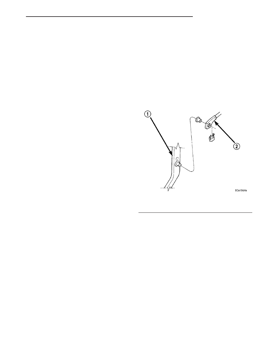
(4) Remove retainer clip securing booster push rod

to pedal (Fig. 46) and clutch rod retainer clip if
equipped.

(5) Remove bolts from brake pedal support and

booster mounting nuts. Remove mounting stud plate
nuts or clutch cylinder mounting nuts if equipped.

(6) Slid brake booster/master cylinder assembly

forward.

(7) Remove mounting stud plate or slid clutch cyl-

inder forward if equipped.

(8) Tilt the pedal support down to gain shaft clear-

ance.

(9) Remove pedal shaft C–clip from passenger side

of the shaft.

(10) Slide the pedal shaft toward the drivers side

and remove the remaining C-clip.

(11) Slid the shaft out of the pedal bracket and

remove the pedal.

(12) Remove pedal bushings if they are to be

replaced.

INSTALLATION

(1) Install new bushings in pedal. Lubricate bush-

ings and shaft with multi-purpose grease.

(2) Position pedal in bracket and install shaft.
(3) Install new pivot pin C-clip.
(4) Position pedal support and install support bolts

and tighten to 28 N·m (21 ft. lbs.).

(5) Slid the booster/master cylinder assembly into

place, install mounting nuts and tighten to 39 N·m
(29 ft. lbs.).

(6) Install stud plate or clutch cylinder if equipped

and tighten mounting nut to 28 N·m (21 ft. lbs.).

Install retainer clip securing booster push rod to

pedal (Fig. 46) and clutch rod retainer clip if
equipped.

(7) Install ABS controller if equipped.
(8) Install and connect brake lamp switch.
(9) Install negative battery cable.

Fig. 46 Push Rod Attachment

1 - BRAKE PEDAL
2 - BOOSTER ROD

TJ

BRAKES - BASE

5 - 25

MASTER CYLINDER (Continued)

POWER BRAKE BOOSTER

DESCRIPTION

The booster assembly consists of a housing divided

into separate chambers by two internal diaphragms.
The outer edge of each diaphragm is attached to the
booster housing.

Two push rods are used in the booster. The pri-

mary push rod connects the booster to the brake
pedal. The secondary push rod connects the booster
to the master cylinder to stroke the cylinder pistons.

OPERATION

The atmospheric inlet valve is opened and closed

by the primary push rod. Booster vacuum supply is
through a hose attached to an intake manifold fitting
at one end and to the booster check valve at the
other. The vacuum check valve in the booster housing
is a one-way device that prevents vacuum leak back.

Power assist is generated by utilizing the pressure

differential between normal atmospheric pressure
and a vacuum. The vacuum needed for booster oper-
ation is taken directly from the engine intake mani-
fold. The entry point for atmospheric pressure is
through a filter and inlet valve at the rear of the
housing (Fig. 47).

Fig. 47 Power Brake Booster–Typical

1 - VACUUM CHECK VALVE
2 - FRONT DIAPHRAGM
3 - REAR DIAPHRAGM
4 - HOUSING
5 - SEAL
6 - AIR FILTER

7 - PRIMARY PUSH ROD (TO BRAKE PEDAL)
8 - ATMOSPHERIC INLET VALVE ASSEMBLY
9 - BOOSTER MOUNTING STUDS (4)
10 - SECONDARY PUSH ROD (TO MASTER CYLINDER)
11 - MASTER CYLINDER MOUNTING STUD (2)
12 - SPRING

5 - 26

BRAKES - BASE

TJ

The chamber areas forward of the booster dia-

phragms are exposed to vacuum from the intake
manifold. The chamber areas to the rear of the dia-
phragms, are exposed to normal atmospheric pres-
sure of 101.3 kilopascals (14.7 pounds/square in.).

Brake pedal application causes the primary push

rod to open the atmospheric inlet valve. This exposes
the area behind the diaphragms to atmospheric pres-
sure. The resulting pressure differential provides the
extra apply force for power assist.

The booster check valve, check valve grommet and

booster seals are serviceable.

REMOVAL

(1) Remove combination valve and master cylinder.
(2) Disconnect vacuum hose from booster check

valve.

(3) Remove retaining clip that secures booster

push rod to brake pedal (Fig. 48) and slide the rod off
the pin.

(4) Remove four nuts attaching booster to front

cowl panel (Fig. 49).

(5) In engine compartment, slide booster studs out

of cowl panel, and remove the booster from engine
compartment.

(6) Remove dash seal from booster.

INSTALLATION

(1) Clean the booster mounting surface.
(2) Install dash seal on booster.
(3) Align and position booster on the front cowl

panel.

(4) In passenger compartment, install nuts that

attach booster to dash panel. Tighten nuts just
enough to hold booster in place.

(5) Lubricate the pedal pin and bushing with

Mopar multi-mileage grease. Then slid the booster

push rod onto brake pedal pin and secure with
retaining clip.

(6) Tighten booster mounting nuts to 39 N·m (29

ft. lbs.).

(7) Connect vacuum hose to booster check valve.
(8) Install master cylinder and combination valve.
(9) Top off master cylinder fluid level and bleed

base brakes.

COMBINATION VALVE

DESCRIPTION

The combination valve contains a pressure differ-

ential valve and switch and a rear brake proportion-
ing valve. The valve is not repairable and must be
replaced as an assembly if diagnosis indicates this is
necessary.

OPERATION

PRESSURE DIFFERENTIAL VALVE

The pressure differential switch is connected to the

brake warning light. The switch is actuated by move-
ment of the switch valve. The switch monitors fluid
pressure in the separate front/rear brake hydraulic
circuits.

A decrease or loss of fluid pressure in either

hydraulic circuit will cause the switch valve to shut-
tle to the low pressure side. Movement of the valve
pushes the switch plunger upward. This action closes
the switch internal contacts completing the electrical
circuit to the red warning light. The switch valve will
remain in an actuated position until repairs to the
brake system are made.

Fig. 48 Push Rod & Clip

1 - BRAKE PEDAL
2 - BOOSTER ROD

Fig. 49 Booster Mounting Nuts

1 - BOOSTER
2 - BRAKE PEDAL

TJ

BRAKES - BASE

5 - 27

POWER BRAKE BOOSTER (Continued)

PROPORTIONING VALVE

The proportioning valve is used to balance front-

rear brake action at high decelerations. The valve
allows normal fluid flow during moderate braking.
The valve only controls fluid flow during high decel-
erations brake stops.

DIAGNOSIS AND TESTING - COMBINATION
VALVE

Pressure Differential Switch

(1) Have helper sit in drivers seat to apply brake

pedal and observe red brake warning light.

(2) Raise vehicle on hoist.
(3) Connect bleed hose to a rear wheel cylinder

and immerse hose end in container partially filled
with brake fluid.

(4) Have helper press and hold brake pedal to floor

and observe warning light.

(a) If warning light illuminates, switch is operat-

ing correctly.

(b) If light fails to illuminate, check circuit fuse,

bulb, and wiring. The parking brake switch can be
used to aid in identifying whether or not the brake
light bulb and fuse is functional. Repair or replace
parts as necessary and test differential pressure
switch operation again.
(5) If warning light still does not illuminate,

switch is faulty. Replace combination valve assembly,
bleed brake system and verify proper switch and
valve operation.

REMOVAL

(1) Remove brake lines that connect master cylin-

der to combination valve (Fig. 50).

(2) Disconnect brake lines that connect combina-

tion valve to front and rear brakes.

(3) Disconnect wire from combination valve switch

terminal. Be careful when separating wire connector
as lock tabs are easily damaged if not fully disen-
gaged.

(4) Remove

nuts

attaching

combination

valve

bracket to booster studs and remove valve bracket off
booster studs (Fig. 51).

INSTALLATION

(1) Position valve bracket on booster studs and

tighten bracket attaching nuts to 20 N·m (15 ft. lbs.).

(2) Align and start brake line fittings in combina-

tion valve and master cylinder by hand to avoid cross
threading.

(3) Tighten brake line fittings at combination valve

to 19 N·m (14 ft. lbs.).

(4) Tighten brake line fittings at master cylinder

to 19 N·m (14 ft. lbs.).

(5) Connect wire to differential pressure switch in

combination valve.

(6) Bleed base brake system. (Refer to 5 - BRAKES

- STANDARD PROCEDURE).

ROTORS

DIAGNOSIS AND TESTING

DIAGNOSIS AND TESTING - DISC BRAKE
ROTOR

The rotor braking surfaces should not be refinished

unless necessary.

Light surface rust and scale can be removed with a

lathe equipped with dual sanding discs. The rotor

Fig. 50 Combination Valve/Master Cylinder

1 - COMBINATION VALVE
2 - MASTER CYLINDER

Fig. 51 Combination Valve Bracket

1 - MASTER CYLINDER
2 - COMBINATION VALVE BRACKET

5 - 28

BRAKES - BASE

TJ

COMBINATION VALVE (Continued)


Content   ..  250  251  252  253   ..