Jeep Wrangler TJ. Manual - part 248


  Index      Jeep     Jeep Wrangler TJ - service repair manual 2005 year


Search            


Content   ..  246  247  248  249   ..


Jeep Wrangler TJ. Manual - part 248


(3) Install replacement tube nut on the tube.
(4) Insert tube in flaring tool.
(5) Place gauge form over the end of the tube.
(6) Push tubing through flaring tool jaws until

tube contacts recessed notch in gauge that matches
tube diameter.

(7) Tighten the tool bar on the tube
(8) Insert plug on gauge in the tube. Then swing

compression disc over gauge and center tapered flar-
ing screw in recess of compression disc (Fig. 3).

(9) Tighten

tool

handle

until

plug

gauge

is

squarely seated on jaws of flaring tool. This will start
the inverted flare.

(10) Remove the plug gauge and complete the

inverted flare.

STANDARD PROCEDURE - ISO FLARING

A preformed metal brake tube is recommended and

preferred for all repairs. However, double-wall steel
tube can be used for emergency repair when factory
replacement parts are not readily available.

To make a ISO flare use a Flaring Tool kit.
(1) Cut off damaged tube with Tubing Cutter.
(2) Remove any burrs from the inside of the tube.
(3) Install tube nut on the tube.
(4) Position the tube in the flaring tool flush with

the top of the tool bar (Fig. 4). Then tighten the tool
bar on the tube.

(5) Install the correct size adaptor on the flaring

tool yoke screw.

(6) Lubricate the adaptor.
(7) Align the adaptor and yoke screw over the tube

(Fig. 4).

(8) Turn the yoke screw in until the adaptor is

squarely seated on the tool bar.

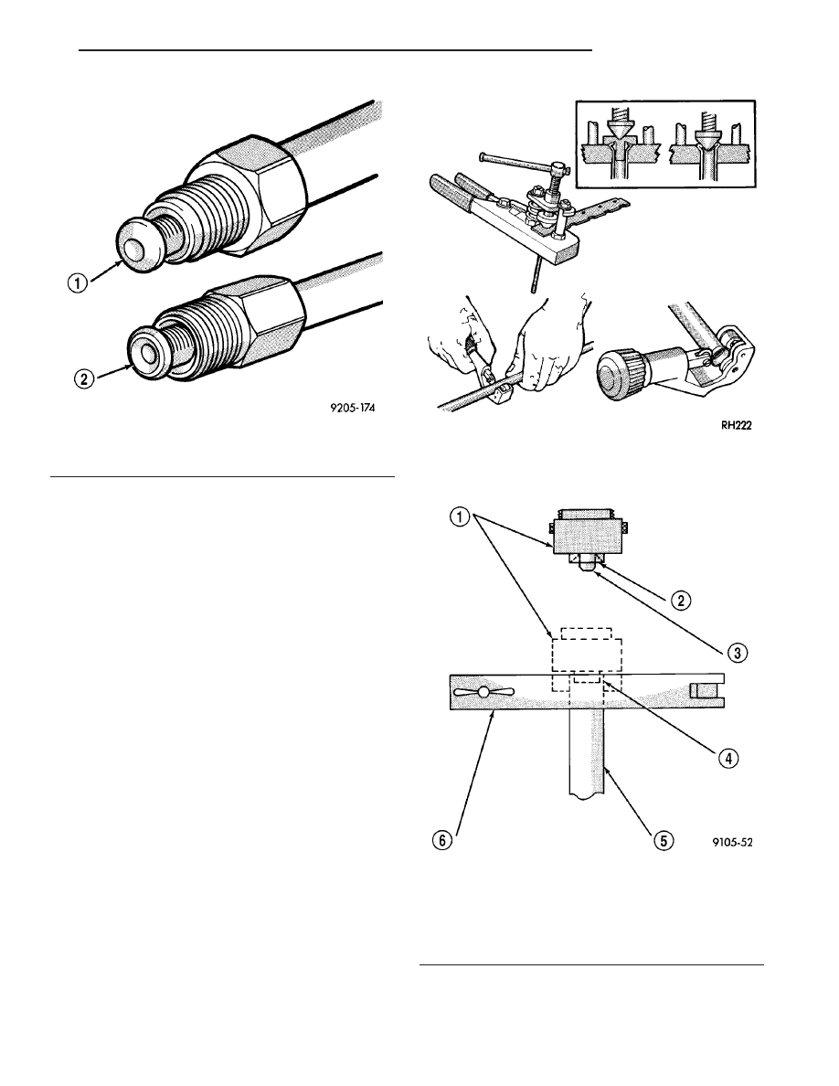
Fig. 2 Inverted Flare And ISO Flare

1 - ISO-STYLE FLARE
2 - DOUBLE INVERTED-STYLE FLARE

Fig. 3 Inverted Flare Tools

Fig. 4 ISO Flaring

1 - ADAPTER
2 - LUBRICATE HERE
3 - PILOT
4 - FLUSH WITH BAR
5 - TUBING
6 - BAR ASSEMBLY

TJ

BRAKES - BASE

5 - 9

BRAKE LINES (Continued)

DISC BRAKE CALIPERS

DESCRIPTION

The calipers are a single piston type. The calipers

are free to slide laterally, this allows continuous com-
pensation for lining wear.

OPERATION

When the brakes are applied fluid pressure is

exerted against the caliper piston. The fluid pressure
is exerted equally and in all directions. This means
pressure exerted against the caliper piston and
within the caliper bore will be equal (Fig. 5).

Fluid pressure applied to the piston is transmitted

directly to the inboard brake shoe. This forces the
shoe lining against the inner surface of the disc
brake rotor. At the same time, fluid pressure within
the piston bore forces the caliper to slide inward on
the mounting bolts. This action brings the outboard
brake shoe lining into contact with the outer surface
of the disc brake rotor.

In summary, fluid pressure acting simultaneously

on both piston and caliper, produces a strong clamp-
ing action. When sufficient force is applied, friction
will attempt to stop the rotors from turning and
bring the vehicle to a stop.

Application and release of the brake pedal gener-

ates only a very slight movement of the caliper and
piston. Upon release of the pedal, the caliper and pis-
ton return to a rest position. The brake shoes do not
retract an appreciable distance from the rotor. In
fact, clearance is usually at, or close to zero. The rea-
sons for this are to keep road debris from getting
between the rotor and lining and in wiping the rotor
surface clear each revolution.

The caliper piston seal controls the amount of pis-

ton extension needed to compensate for normal lining
wear.

During brake application, the seal is deflected out-

ward by fluid pressure and piston movement (Fig. 6).
When the brakes (and fluid pressure) are released,
the seal relaxes and retracts the piston.

The amount of piston retraction is determined by

the amount of seal deflection. Generally the amount
is just enough to maintain contact between the pis-
ton and inboard brake shoe.

REMOVAL

REMOVAL - FRONT

(1) Raise and support vehicle.
(2) Remove front wheel and tire assembly.
(3) Drain small amount of fluid from master cylin-

der brake reservoir with suction gun.

(4) Bottom caliper piston in bore with C-clamp.

Position clamp screw on outboard brake shoe and
clamp frame on rear of caliper (Fig. 7). Do not allow
clamp screw to bear directly on outboard shoe
retainer spring. Use wood or metal spacer
between shoe and clamp screw.

Fig. 5 Brake Caliper Operation

1 - CALIPER
2 - PISTON
3 - PISTON BORE
4 - SEAL
5 - INBOARD SHOE
6 - OUTBOARD SHOE

Fig. 6 Lining Wear Compensation By Piston Seal

1 - PISTON
2 - CYLINDER BORE
3 - PISTON SEAL BRAKE PRESSURE OFF
4 - CALIPER HOUSING
5 - DUST BOOT
6 - PISTON SEAL BRAKE PRESSURE ON

5 - 10

BRAKES - BASE

TJ

(5) Remove brake hose mounting bolt and discard

washers (Fig. 8).

(6) Remove caliper mounting bolts (Fig. 9).
(7) Tilt top of caliper outward with pry tool if nec-

essary (Fig. 10) and remove caliper.

(8) Remove caliper from vehicle.

REMOVAL - REAR

(1) Install prop rod on the brake pedal to keep

pressure on the brake system.

(2) Raise and support vehicle.
(3) Remove the wheel and tire assembly.
(4) Remove the brake hose banjo bolt if replacing

caliper.

(5) Remove the caliper mounting slide pin bolts

(Fig. 11).

(6) Remove the caliper from vehicle.

Fig. 7 Bottoming Caliper Piston With C-Clamp

1 - CALIPER BOSS
2 - OUTBOARD BRAKESHOE
3 - C-CLAMP

Fig. 8 Brake Hose And Bolt

1 - FITTING WASHERS
2 - CALIPERS

Fig. 9 Caliper Mounting Bolts

1 - CALIPER MOUNTING BOLT (2)
2 - CALIPER

Fig. 10 Caliper Removal

1 - TILT CALIPER OUTBOARD TO REMOVE

TJ

BRAKES - BASE

5 - 11

DISC BRAKE CALIPERS (Continued)

DISASSEMBLY

(1) Remove brake shoes from caliper.
(2) Drain brake fluid out of caliper.
(3) Take a piece of wood and pad it with one-inch

thickness of shop towels. Place this piece in the out-
board shoe side of the caliper in front of the piston.
This will cushion and protect caliper piston during
removal (Fig. 12).

(4) Remove caliper piston with short bursts of

low pressure compressed air. Direct air through fluid
inlet port and ease piston out of bore (Fig. 13).

CAUTION: Do not blow the piston out of the bore
with sustained air pressure. This could result in a
cracked piston. Use only enough air pressure to
ease the piston out.

WARNING: NEVER ATTEMPT TO CATCH THE PIS-
TON AS IT LEAVES THE BORE. THIS MAY RESULT
IN PERSONAL INJURY.

(5) Remove caliper piston dust boot with suitable

pry tool (Fig. 14).

(6) Remove caliper piston seal with wood or plastic

tool (Fig. 15). Do not use metal tools as they will
scratch piston bore.

Fig. 11 CALIPER MOUNTING

1 - BRAKE HOSE
2 - CALIPER MOUNTING BOLTS
3 - BANJO BOLT

Fig. 12 Padding Caliper Interior

1 - SHOP TOWELS OR CLOTHS
2 - CALIPER

Fig. 13 Caliper Piston Removal

1 - AIR GUN
2 - CALIPER PISTON
3 - PADDING MATERIAL

Fig. 14 Caliper

1 - COLLAPSE BOOT WITH PUNCH OR SCREWDRIVER
2 - PISTON DUST BOOT

5 - 12

BRAKES - BASE

TJ

DISC BRAKE CALIPERS (Continued)


Content   ..  246  247  248  249   ..