Jeep Wrangler TJ. Manual - part 242


  Index      Jeep     Jeep Wrangler TJ - service repair manual 2005 year


Search            


Content   ..  240  241  242  243   ..


Jeep Wrangler TJ. Manual - part 242


(6) Lubricated and install disc without threaded

hole from Trac-Lok

t Tool C-4487 into lower side gear.

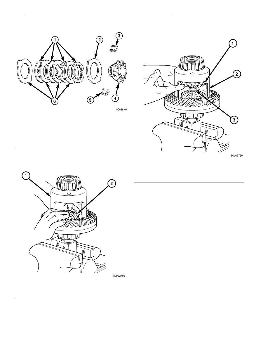
(7) Install upper side gear and clutch disc pack

with retaining clips seated in the case pockets (Fig.
59).

(8) Hold assembly in position and install threaded

disc from Trac-Lok

t Tool C-4487 into top side gear.

(9) Install forcing screw and tighten screw to

slightly compress clutch disc.

(10) Place pinion gears in position in side gears

and verify that the pinion mate shaft hole is aligned.

(11) Rotate case with turning bar C-4487-2 until

pinion mate shaft holes in pinion gears align with
holes in case. It may be necessary to slightly tighten
the forcing screw in order to install the pinion gears.

(12) Tighten forcing screw to 122 N·m (90 ft. lbs.)

maximum to compress the Belleville springs.

(13) Lubricate and install thrust washers behind

pinion gears and align washers with a small screw
driver. Insert mate shaft into each pinion gear to ver-
ify alignment.

(14) Remove

Forcing

Screw,

Step

Plate

and

Threaded Adapter.

(15) Install pinion gear mate shaft and align holes

in shaft and case.

(16) Install pinion mate shaft roll pin. Stake (peen)

case over pin in two places 180 degrees apart.

(17) Lubricate all differential components with

hypoid gear lubricant.

Fig. 57 CLUTCH PACK

1 - DISCS
2 - DISHED PLATE
3 - RETAINER
4 - SIDE GEAR
5 - RETAINER
6 - PLATES

Fig. 58 CLUTCH PACK AND LOWER SIDE GEAR

1 - DIFFERENTIAL CASE
2 - SIDE GEAR AND CLUTCH PACK

Fig. 59 CLUTCH PACK AND UPPER SIDE GEAR

1 - SIDE GEAR AND CLUTCH PACK
2 - DIFFERENTIAL CASE
3 - DISC

TJ

REAR AXLE - 216RBI

3 - 145

DIFFERENTIAL -TRAC-LOK (Continued)

DIFFERENTIAL - TRU-LOK

DESCRIPTION

The differential is a locking differential, that pro-

vides a positive mechanical connection between the
right and left axle when engauged. The differential
uses a dog clutch to connection the right and left
axle.

OPERATION

The Tru-lok differential is activated by the axle

lock switch located on the dash panel. When the
switch is activated, an air pump with a built-in pres-
sure regulator sends 5 PSI of air pressure to a accua-
tor diaphragm in the differential housing. The
diaphragm then engages a dog clutch and a position
switch. The dog clutch has one gear attached to the
differential case and another gear attached to a dif-
ferential side gear. When the dog clutch is engaged
the right and left wheels turn at the same speed. The
position switch lights a lamp on the dash to indicate
the system has been engaged. The differential works
as standard differential when not engaged.

NOTE: The differential is serviced as an assembly,
the diaphragm and indicator switch are serviced
separately. The differential case must be removed
to service the diaphragm actuator and indicator
switch.

DIAGNOSIS AND TESTING

UNLOCKED

(1) Block tires opposite the axle to be tested to pre-

vent the vehicle from rolling.

(2) Place transfer case in 4WD Low and automan-

tic transmission in Park (1st gear if manual trans-
mission).

(3) Raise both wheels of the axle to be tested off

the ground.

(4) Turn ignition to the ON position and dash

switch to the OFF position.

(5) Rotate one tire by hand. The other tire should

spin in the opposite direction.

NOTE: If wheel cannot be rotated the differential
must be repaired/replaced.

LOCKED

(1) Block tires opposite the axle to be tested to pre-

vent the vehicle from rolling.

(2) Place transfer case in 4WD Low and automan-

tic transmission in Park (1st gear if manual trans-
mission).

(3) Raise both wheels of the axle to be tested off

the ground.

(4) Turn ignition to the ON position and dash

switch to the ON position.

(5) Try to rotate one tire by hand. You should not

be able to rotate the tire.

NOTE: If wheel does rotated verify locker pump
operation. If the pump is fuctional the differential
must be repaired/replaced.

TRU-LOK INDICATOR SWITCH

(1) Turn ignition switch off.
(2) Disconnect indicator switch harness (Fig. 60)

from the differential housing.

(3) Measure electrical continuity across the switch

terminals. Circuit should be closed (zero resistance).

NOTE: If circuit is not closed replace indicator
switch.

Fig. 60 INDICATOR SWITCH CONNECTOR

1 - CONNECTOR
2 - DIFFERENTIAL COVER

3 - 146

REAR AXLE - 216RBI

TJ

TRU-LOK PUMPS

(1) Connect a pressure gauge to the rear pump.
(2) Place transfer case in 4WD Low and automatic

transmission in Park (1st gear if manual transmis-
sion).

(3) Turn ignition to the ON position and push the

dash switch to activate the rear pump.

NOTE: If pump is not running, verify pump has (Fig.
61) 12 volts and ground.

(4) With the pump running the pressure gauge

should show 5 psi..

NOTE: If pump does not produce 5 psi. replace the
pump.

REMOVAL

(1) Remove drain plug from the differential hous-

ing.

(2) Disconnect

indicator

switch

harness

and

remove connector from differential cover (Fig. 62).

(3) Remove differential housing cover.
(4) Remove axle shafts.
(5) Remove pressure hose from actuator assembly

(Fig. 63).

Fig. 61 PUMP CONNECTORS

1 - REAR PUMP CONNECTOR
2 - FRONT PUMP CONNECTOR
3 - AXLE HARNESS

Fig. 62 INDICATOR SWITCH CONNECTOR

1 - CONNECTOR
2 - DIFFERENTIAL COVER

Fig. 63 PRESSURE HOSE

1 - PRESSURE HOSE
2 - BEARING CAP
3 - PRESSURE HOSE CLAMP

TJ

REAR AXLE - 216RBI

3 - 147

DIFFERENTIAL - TRU-LOK (Continued)

(6) Note the reference letters stamped on the bearing

caps and housing machined sealing surface (Fig. 64).

(7) Loosen differential bearing cap bolts.
(8) Position Spreader W-129-B with Adapter Kit

6987B on differential locating holes (Fig. 65). Install
hold-down clamps and tighten the turnbuckle finger-
tight.

(9) Install a Pilot Stud C-3288-B at the left side of

the differential housing. Attach Dial Indicator C-3339
to pilot stud (Fig. 66). Load indicator plunger against
the opposite side of the housing and zero the indica-
tor.

CAUTION: Never spread the housing over 0.38 mm
(0.015 in). Failure to heed caution may result in
damage.

(10) Spread housing while measuring the distance

with the dial indicator (Fig. 67).

(11) Remove dial indicator.
(12) Remove differential bearing cap bolts and ring

gear side bearing cap.

(13) Remove differential from housing with pinion

gear side bearing cap (Fig. 68) and tag differential
bearing cups and preload shims to indicate location.

CAUTION: Do not bend actuator mounting tabs,
during differential removal. Failure to heed caution
may result in damage.

(14) Remove spreader from housing.
(15) Remove indicator switch (Fig. 69) from differ-

ential housing.

(16) Clean the housing cavity with flushing oil,

light engine oil or lint free cloth.

NOTE: Do not use water, steam, kerosene or gaso-
line for cleaning.

DISASSEMBLY

(1) Install Plug C-293-3 into the differential axle

shaft hole.

Fig. 64 LOCATION MARKS

1 - REFERENCE MARKS
2 - REFERENCE MARKS

Fig. 65 SPREADER LOCATION

1 - DIFFERENTIAL CASE
2 - ADAPTER
3 - HOLD DOWN
4 - SPREADER
5 - TURNBUCKLE

Fig. 66 DIAL INDICATOR LOCATION

1 - DIAL INDICATOR
2 - PILOT STUD

3 - 148

REAR AXLE - 216RBI

TJ

DIFFERENTIAL - TRU-LOK (Continued)


Content   ..  240  241  242  243   ..