Jeep Wrangler TJ. Manual - part 232


  Index      Jeep     Jeep Wrangler TJ - service repair manual 2005 year


Search            


Content   ..  230  231  232  233   ..


Jeep Wrangler TJ. Manual - part 232


DIFFERENTIAL COVER

REMOVAL

(1) With vehicle in neutral, position vehicle on hoist.
(2) Remove drain plug.
(3) Remove cover bolts.
(4) Remove cover and drain lubricant.

INSTALLATION

(1) Apply a 6.35mm (1/4 in.) bead of Mopar Sili-

cone Rubber Sealant or equivalent to the housing
cover (Fig. 39).

CAUTION: If housing cover is not installed within 3
to 5 minutes, the cover must be cleaned and new
RTV applied. Failure to heed caution may result in
damage.

(2) Install cover and identification tag. Tighten

cover bolts in a criss-cross pattern to 41 N·m (30 ft.
lbs.).

(3) Fill differential to specifications.
(4) Install fill plug and tighten to 34 N·m (25 ft.

lbs.).

DIFFERENTIAL

REMOVAL

(1) Remove differential fill plug.
(2) Remove differential cover and drain fluid.

(3) Remove axle shafts.
(4) Note reference letters stamped on the bearing

caps and housing machined sealing surface (Fig. 40).

(5) Loosen differential bearing cap bolts.
(6) Position Spreader W-129-B with Adapter Kit

6987B on differential locating holes (Fig. 41). Install
hold-down clamps and tighten the turnbuckle finger-
tight.

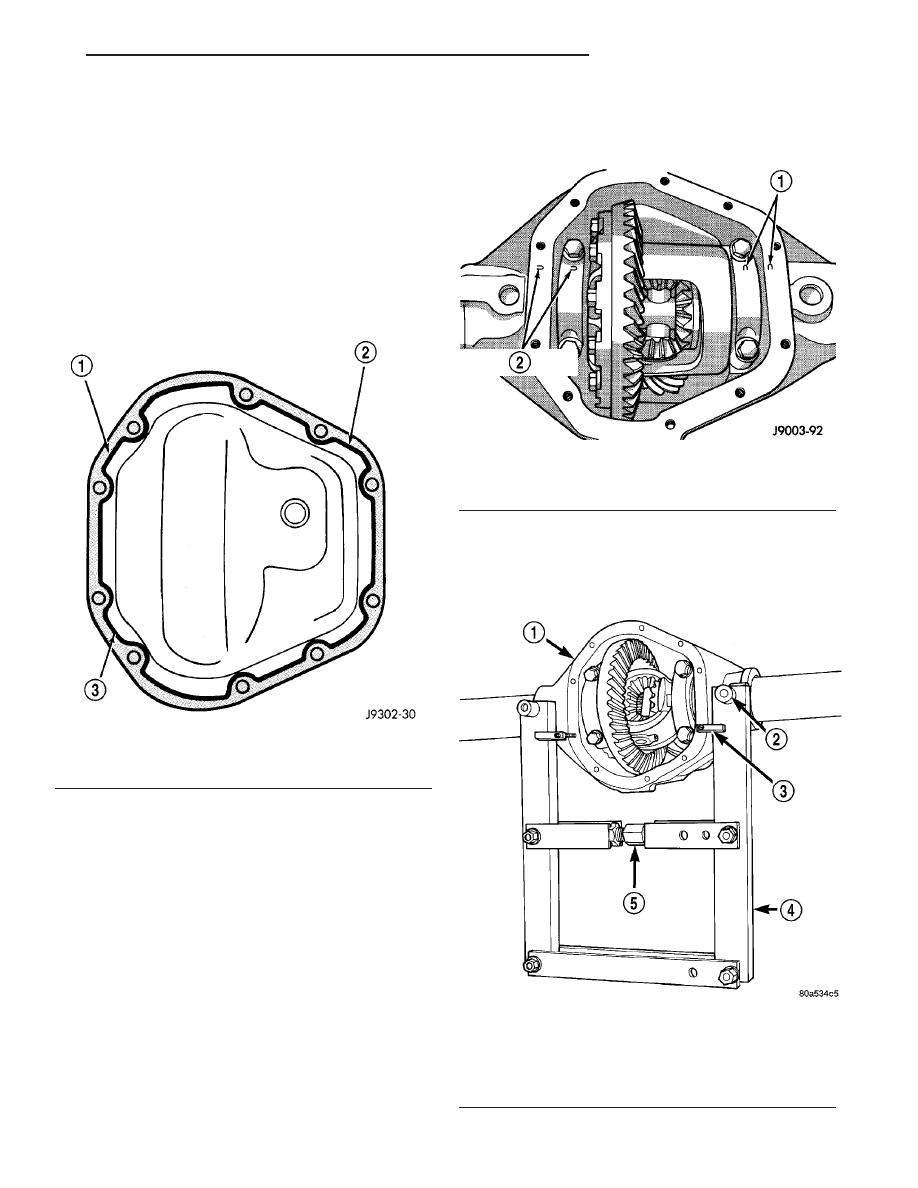
Fig. 39 HOUSING COVER - TYPICAL

1 - SEALANT SURFACE
2 - SEALANT
3 - SEALANT THICKESS

Fig. 40 BEARING CAP REFERENCE

1 - REFERENCE LETTERS
2 - REFERENCE LETTERS

Fig. 41 SPREADER LOCATION

1 - DIFFERENTIAL HOUSING
2 - DOWEL
3 - SAFETY HOLD DOWN
4 - SPREADER
5 - TURNBUCKLE

TJ

REAR AXLE - 194RBI

3 - 105

(7) Install a Pilot Stud C-3288-B at the left side of

the differential housing. Attach Dial Indicator C-3339 to
pilot stud. Load indicator plunger against the opposite
side of the housing (Fig. 42) and zero the indicator.

CAUTION: Never spread the housing over 0.38 mm
(0.015 in). Failure to heed caution may result in
damage.

(8) Spread housing while measuring the distance

with the dial indicator (Fig. 43).

(9) Remove dial indicator.
(10) While holding differential case in position,

remove differential bearing caps.

(11) Remove differential from housing and tag dif-

ferential bearing cups to indicate location (Fig. 44).

(12) Remove spreader from housing.
(13) Clean the housing cavity with flushing oil,

light engine oil or lint free cloth.

NOTE: Do not use water, steam, kerosene or gaso-
line for cleaning.

DISASSEMBLY

(1) Remove pinion shaft.
(2) Rotate differential side gears and remove dif-

ferential pinions and thrust washers (Fig. 45).

(3) Remove differential side gears and thrust

washers.

ASSEMBLY

(1) Lubricate

all

differential

components

with

hypoid gear lubricant.

(2) Install differential side gears and thrust wash-

ers.

(3) Install differential pinion gears and thrust

washers.

(4) Install the pinion mate shaft.
(5) Align hole in the pinion mate shaft with the

hole in the differential case and install pinion mate
shaft lock screw finger tight.

Fig. 42 DIAL INDICATOR LOCATION

1 - CLAMP
2 - DIAL INDICATOR
3 - LEVER ADAPTER
4 - SPREADER
5 - PILOT STUD

Fig. 43 SPREAD DIFFERENTIAL HOUSING

1 - DIAL INDICATOR
2 - SPREADER

Fig. 44 DIFFERENTIAL CASE REMOVAL

1 - DIFFERENTIAL HOUSING
2 - DIFFERENTIAL CASE
3 - BEARING CUPS

3 - 106

REAR AXLE - 194RBI

TJ

DIFFERENTIAL (Continued)

INSTALLATION

NOTE: If replacement differential bearings or differ-
ential case are being installed, differential side
bearing shim requirements may change. Refer
Adjustments (Differential Bearing Preload and Gear
Backlash) to determine the proper shim selection.

(1) Position Spreader W-129-B and adapters from

Adapter set 6987, with the tool dowel pins seated in
the locating holes (Fig. 46). Install hold-down clamps
and tighten turnbuckle finger-tight.

(2) Install Pilot Stud C-3288-B at the left side of

the differential housing. Attach Dial Indicator C-3339
to pilot stud. Load the indicator plunger against the
opposite side of the housing and zero the indicator.

CAUTION: Never spread over 0.38 mm (0.015 in).
Failure to heed caution may result in damage.

(3) Spread the housing enough to install the case

in the housing. Measure the distance with the dial
indicator.

(4) Remove the dial indicator.
(5) Install differential case in the housing. Ensure

that the differential bearing cups remain in position
on the differential bearings. Tap the differential case
to ensure the bearings cups are seated in the hous-
ing.

(6) Install bearing caps in their original locations

(Fig. 47).

(7) Loosely install differential bearing cap bolts.
(8) Remove axle housing spreader.
(9) Tighten bearing cap bolts to 77 N·m (57 ft.

lbs.).

(10) Install axle shafts.
(11) Install cover and identification tag.

Fig. 45 DIFFERENTIAL GEARS

1 - THRUST WASHER
2 - SIDE GEAR
3 - DIFFERENTIAL PINION

Fig. 46 SPREADER LOCATION

1 - DIFFERENTIAL HOUSING
2 - DOWEL
3 - SAFETY HOLD DOWN
4 - SPREADER
5 - TURNBUCKLE

Fig. 47 BEARING CAP REFERENCE

1 - REFERENCE LETTERS
2 - REFERENCE LETTERS

TJ

REAR AXLE - 194RBI

3 - 107

DIFFERENTIAL (Continued)

DIFFERENTIAL - TRAC-LOK

DESCRIPTION

The Trac-Lok

t differential has a one-piece differen-

tial case, and similar internal components as a stan-
dard

differential,

plus

two

clutch

disc

packs.

Differential bearing preload and ring gear backlash
are adjusted with shims located between the differ-
ential case bearing cups and housing. Pinion bearing
preload is set and maintained by the use of a collaps-
ible spacer.

OPERATION

This differentials clutches are engaged by two con-

current forces. The first being the preload force
exerted through Belleville spring washers within the
clutch packs. The second is the separating forces gen-
erated by the side gears as torque is applied through
the ring gear (Fig. 48).

This design provides the differential action needed

for turning corners and for driving straight ahead
during periods of unequal traction. When one wheel
looses traction, the clutch packs transfer additional
torque to the wheel having the most traction. This
differential resist wheel spin on bumpy roads and
provide more pulling power when one wheel looses
traction. Pulling power is provided continuously until
both wheels loose traction. If both wheels slip due to
unequal traction, Trac-lok

t operation is normal. In

extreme cases of differences of traction, the wheel
with the least traction may spin.

DIAGNOSIS AND TESTING

The most common problem is a chatter noise when

turning corners. Before removing the unit for repair,
drain, flush and refill the axle with the specified
lubricant. A container of Mopar Trac-lok

t Lubricant

(friction modifier) should be added after repair ser-
vice or during a lubricant change.

After changing the lubricant, drive the vehicle and

make 10 to 12 slow, figure-eight turns. This maneu-
ver will pump lubricant through the clutches. This
will correct the condition in most instances. If chatter
persists, clutch damage could have occurred.

DIFFERENTIAL TEST

The differential can be tested without removing the

differential case by measuring rotating torque. Make

sure brakes are not dragging during this measure-
ment.

(1) Place blocks in front and rear of both front

wheels.

(2) Raise one rear wheel until it is completely off

the ground.

(3) Engine off, transmission in neutral, and park-

ing brake off.

(4) Remove wheel and bolt Special Tool 6790 or

equivalent tool to studs.

Fig. 48 TRAC-LOK LIMITED SLIP DIFFERENTIAL

1 - CASE
2 - RING GEAR
3 - DRIVE PINION
4 - PINION GEAR
5 - MATE SHAFT
6 - CLUTCH PACK
7 - SIDE GEAR
8 - CLUTCH PACK

3 - 108

REAR AXLE - 194RBI

TJ


Content   ..  230  231  232  233   ..