Jeep Wrangler TJ. Manual - part 204


  Index      Jeep     Jeep Wrangler TJ - service repair manual 2005 year


Search            


Content   ..  202  203  204  205   ..


Jeep Wrangler TJ. Manual - part 204


(3) Install the upper grommet and retainer on the

stud and install the nut and tighten to 23 N·m (17 ft.
lbs.).

SPRING

DESCRIPTION

The coil springs mount up in the wheelhouse which

is part of the unitized body bracket. A rubber dough-
nut isolator is located between the top of the spring
and the bracket. The bottom of the spring seats on a
axle pad.

OPERATION

The coil springs control ride quality and maintain

proper ride height. The isolators provide road noise
isolation.

REMOVAL

(1) Raise and support the vehicle.
(2) Remove the wheel and tire assemblies.
(3) Position a hydraulic jack under the axle to sup-

port it.

(4) Remove the front shocks at the lower mount-

ings, (Refer to 2 - SUSPENSION/FRONT/SHOCK -
REMOVAL).

(5) Remove the ABS wire mounting brackets at the

axle. (if equipped)

(6) Remove lower suspension arms mounting nuts

and bolts from the frame, (Refer to 2 - SUSPEN-
SION/FRONT/LOWER

CONTROL

ARM

-

REMOVAL).

(7) Remove the track bar from the axle bracket,

(Refer to 2 - SUSPENSION/FRONT/TRACK BAR -
REMOVAL).

(8) Remove the right side of the drag link from the

right side knuckle, (Refer to 19 - STEERING/LINK-
AGE/DRAG LINK - REMOVAL).

(9) Lower the axle until the spring is free from the

upper mount.

NOTE: Rotation of the spring and prying down
slightly on the axle will aid in removal.

(10) Remove the coil spring retainer clip and

remove the spring.

(11) Remove the upper spring isolator. (if needed)
(12) Pull jounce bumper out of mount. (if needed)

INSTALLATION

(1) Install jounce bumper into mount.
(2) Install the spring isolator.

NOTE: Rotation of the spring and prying down
slightly on the axle will aid in installation.

(3) Position the coil spring on the axle pad. It may

be necessary to rotate the spring while installing.

(4) Install

the

spring

retainer

clip

and

bolt.

Tighten bolt to 21 N·m (16 ft. lbs.).

(5) Raise the axle into position until the spring

seats in the upper mount.

(6) Install the shock at the axle, (Refer to 2 - SUS-

PENSION/FRONT/SHOCK - INSTALLATION).

(7) Install the ABS wire mounting brackets at the

axle (if equipped).

(8) Install the track bar to the axle bracket, (Refer

to 2 - SUSPENSION/FRONT/TRACK BAR - INSTAL-
LATION).

(9) Install the lower suspension arms to the frame.

Install mounting bolts and nuts finger tight, (Refer to
2 - SUSPENSION/FRONT/LOWER CONTROL ARM
- INSTALLATION).

(10) Install the drag link to the right side knuckle,

(Refer to 19 - STEERING/LINKAGE/DRAG LINK -
INSTALLATION).

(11) Remove the hydraulic jack from under the

axle.

(12) Install the wheel and tire assemblies, (Refer

to 22 - TIRES/WHEELS/WHEELS - STANDARD
PROCEDURE).

(13) Remove the supports and lower the vehicle.
(14) Tighten the lower suspension arms nuts to

115 N·m (85 ft. lbs.) at normal ride height with the
vehicle weight.

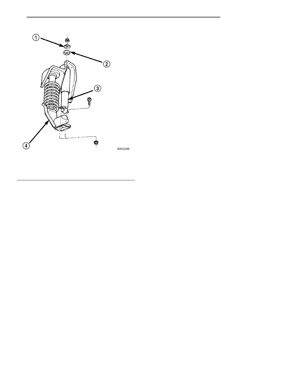
Fig. 8 Coil Spring & Shock Absorber

1 - RETAINER
2 - GROMMET
3 - SHOCK
4 - FRONT AXLE

TJ

FRONT

2 - 13

SHOCK (Continued)

STABILIZER BAR

DESCRIPTION

The spring steel bar extends across the top of the

chassis frame rails. Links are connected from the bar
to the axle brackets. The stabilizer bar and links are
isolated by rubber bushings.

OPERATION

The stabilizer bar is used to control vehicle body

roll during turns. The bar helps to control the vehicle
body in relationship to the suspension.

REMOVAL

(1) Remove upper link nuts (Fig. 9) and separate

the links from the stabilizer bar with Remover
MB-991113.

(2) Remove front bumper valence.
(3) Remove stabilizer retainer bolts (Fig. 9)and

remove retainers.

(4) Remove stabilizer bar.
(5) Remove lower link nuts and bolts and remove

links (Fig. 9).

INSTALLATION

(1) Center stabilizer bar on top of the frame rails

and install retainers and bolts. Tighten bolts to 61
N·m (45 ft. lbs.).

(2) Position links on axle brackets and into the

stabilizer bar. Install lower link bolts and nuts and
tighten to 102 N·m (75 ft. lbs.).

(3) Install upper link nuts and tighten to 61 N·m

(45 ft. lbs.).

(4) Install bumper valence.

TRACK BAR

DESCRIPTION

The bar is attached to a frame rail bracket with a

ball stud and an axle bracket with a bushing. The
bar is forged and has non replaceable isolator bush-
ing and ball stud.

OPERATION

The track bar is used to control front axle lateral

movement and provides cross car location of the axle
assembly.

REMOVAL

(1) Raise and support the vehicle.
(2) Remove the cotter pin and nut from the ball

stud end at the frame rail bracket (Fig. 10).

(3) Use a universal puller tool to separate the

track bar ball stud from the frame rail bracket.

(4) Remove the bolt and flag nut from the axle

bracket (Fig. 10). Remove the track bar.

INSTALLATION

(1) Install the track bar at axle tube bracket.

Loosely install the retaining bolt and flag nut.

(2) It may be necessary to pry the axle assembly

over to install the track bar at the frame rail. Install
track bar at the frame rail bracket. Install the
retaining nut on the stud.

(3) Tighten the ball stud nut to 81N·m (60 ft. lbs.)

and install a new cotter pin.

(4) Remove the supports and lower the vehicle.
(5) Tighten the bolt at the axle bracket to 47 N·m

(40 ft. lbs.).

Fig. 9 Stabilizer Bar

1 - RETAINER
2 - STABILIZER BAR
3 - LINK
4 - BUSHING

Fig. 10 Track Bar

1 - TRACK BAR
2 - FRAME BRACKET
3 - FRONT AXLE

2 - 14

FRONT

TJ

(6) Check alignment if a new track bar was

installed.

(Refer

to

2

-

SUSPENSION/WHEEL

ALIGNMENT - STANDARD PROCEDURE).

UPPER BALL JOINT

REMOVAL

Ball stud service procedures below require removal

of the hub bearing and axle shaft. (Refer to 2 - SUS-
PENSION/FRONT/HUB / BEARING - REMOVAL)
(Refer to 3 - DIFFERENTIAL & DRIVELINE/
FRONT

AXLE

-

181FBI/AXLE

SHAFTS

-

REMOVAL). Removal and installation of upper and
lower ball studs require the use of Tool Kit 6289.

(1) Position tools as shown to remove and install

ball stud (Fig. 11).

UPPER CONTROL ARM

DESCRIPTION

The upper suspension arms are steel and use rub-

ber bushings at each end of the arm. The arms
mount to the frame rail bracket and the axle brack-
ets.

OPERATION

The arm and bushings provide location and react

to loads from the axle. The bushings provide isolation
from the axle.

REMOVAL

(1) Raise and support the vehicle.
(2) Remove the upper suspension arm nut and bolt

at the axle bracket (Fig. 7).

(3) Remove the nut and bolt at the frame rail and

remove the upper suspension arm.

INSTALLATION

(1) Position the upper suspension arm at the axle

and frame rail.

(2) Install the bolts and finger tighten the nuts.
(3) Remove the supports and lower the vehicle.
(4) Tighten the nut at the axle and frame brackets

to 81 N·m (60 ft. lbs.).

Fig. 11 Upper

TJ

FRONT

2 - 15

TRACK BAR (Continued)

REAR

TABLE OF CONTENTS

page

page

REAR

DESCRIPTION

. . . . . . . . . . . . . . . . . . . . . . . . . 16

SPECIFICATIONS

TORQUE CHART

. . . . . . . . . . . . . . . . . . . . . . 16

JOUNCE BUMPER

DESCRIPTION

. . . . . . . . . . . . . . . . . . . . . . . . . 17

OPERATION

. . . . . . . . . . . . . . . . . . . . . . . . . . . 17

LOWER CONTROL ARM

DESCRIPTION

. . . . . . . . . . . . . . . . . . . . . . . . . 17

OPERATION

. . . . . . . . . . . . . . . . . . . . . . . . . . . 17

REMOVAL

. . . . . . . . . . . . . . . . . . . . . . . . . . . . . 17

INSTALLATION

. . . . . . . . . . . . . . . . . . . . . . . . . 17

SHOCK

DESCRIPTION

. . . . . . . . . . . . . . . . . . . . . . . . . 18

OPERATION

. . . . . . . . . . . . . . . . . . . . . . . . . . . 18

DIAGNOSIS AND TESTING - SHOCK

ABSORBER

. . . . . . . . . . . . . . . . . . . . . . . . . . 18

REMOVAL

. . . . . . . . . . . . . . . . . . . . . . . . . . . . . 18

INSTALLATION

. . . . . . . . . . . . . . . . . . . . . . . . . 18

SPRING

DESCRIPTION

. . . . . . . . . . . . . . . . . . . . . . . . . 18

OPERATION

. . . . . . . . . . . . . . . . . . . . . . . . . . . 18

REMOVAL

. . . . . . . . . . . . . . . . . . . . . . . . . . . . . 18

INSTALLATION

. . . . . . . . . . . . . . . . . . . . . . . . . 19

STABILIZER BAR

DESCRIPTION

. . . . . . . . . . . . . . . . . . . . . . . . . 19

OPERATION

. . . . . . . . . . . . . . . . . . . . . . . . . . . 19

REMOVAL

. . . . . . . . . . . . . . . . . . . . . . . . . . . . . 19

INSTALLATION

. . . . . . . . . . . . . . . . . . . . . . . . . 19

TRACK BAR

DESCRIPTION

. . . . . . . . . . . . . . . . . . . . . . . . . 20

OPERATION

. . . . . . . . . . . . . . . . . . . . . . . . . . . 20

REMOVAL

. . . . . . . . . . . . . . . . . . . . . . . . . . . . . 20

INSTALLATION

. . . . . . . . . . . . . . . . . . . . . . . . . 20

UPPER CONTROL ARM

REMOVAL

. . . . . . . . . . . . . . . . . . . . . . . . . . . . . 20

INSTALLATION

. . . . . . . . . . . . . . . . . . . . . . . . . 20

REAR

DESCRIPTION

REAR SUSPENSION

The rear suspension is link/coil design comprised

of:

• Shock absorbers

• Coil springs

• Upper and lower suspension arms

• Stabilizer bar

• Track bar

CAUTION: Suspension components with rubber/ure-
thane bushings (except stabilizer bar) should be
tightened with the vehicle at normal ride height. It is
important to have the springs supporting the weight
of the vehicle when the fasteners are torqued. This
will maintain vehicle ride comfort and prevent pre-
mature bushing wear.

SPECIFICATIONS

TORQUE CHART

TORQUE SPECIFICATIONS

DESCRIPTION

N·m

Ft. Lbs.

In. Lbs.

Shock Absorber

Upper Bolts

35

26

Shock Absorber

Lower Nut

100

74

Suspension Arm Lower

Axle Bracket Nut

203

150

2 - 16

REAR

TJ


Content   ..  202  203  204  205   ..