Jeep Liberty KJ. Manual - part 963


  Index      Jeep     Jeep Liberty KJ - service repair manual 2006 year


Search            


Content   ..  961  962  963  964   ..


Jeep Liberty KJ. Manual - part 963


1. Drain and remove fuel tank. Refer to Fuel Tank

Removal/Installation.

2. Note rotational position of module before attempt-

ing removal. An indexing arrow is located on top of
module for this purpose.

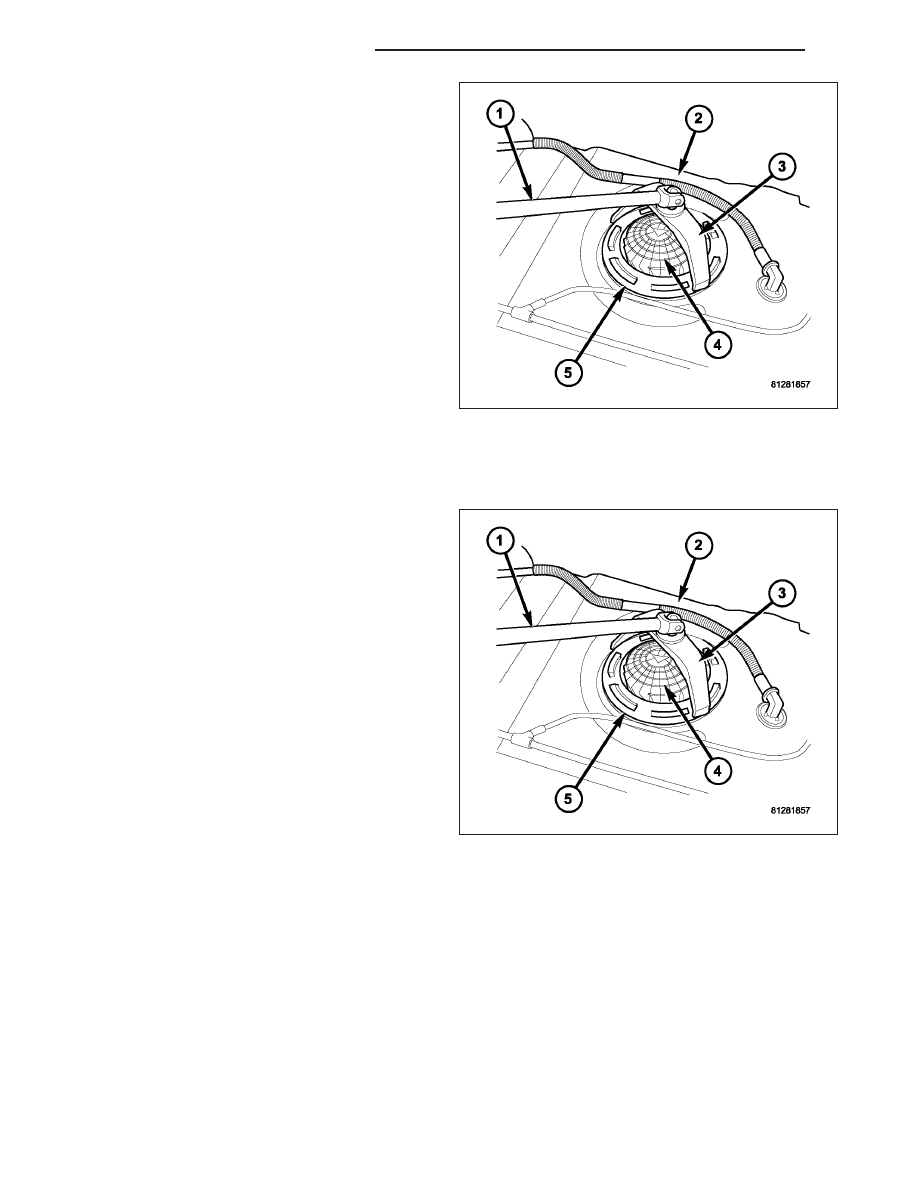
3. Position Special Tool 9340 (3) into notches on out-

side edge of lockring (5).

4. Install 1/2 inch drive breaker bar (1) to tool 9340

(3).

5. Rotate breaker bar counter-clockwise to remove

lockring.

6. Remove lockring. The module will spring up slightly

when lockring is removed.

7. Remove module from fuel tank. Be careful not to

bend float arm while removing.

INSTALLATION

CAUTION: Whenever the fuel pump module is serviced, the rubber seal (gasket) must be replaced.

1. Using a new seal (gasket), position fuel tank mod-

ule into opening in fuel tank.

2. Position lockring (5) over top of fuel pump module.

3. Rotate module until embossed alignment arrow

points to center alignment mark. This step must be
performed to prevent float from contacting side of
fuel tank. Also be sure fuel fitting on top of pump
module is pointed to front of vehicle.

4. Install Special Tool 9340 (3) to lockring.

5. Install 1/2 inch drive breaker (1) into Special Tool

9340 (3).

6. Tighten lockring (clockwise) until all seven notches

have engaged.

7. Install

fuel

tank.

Refer

to

Fuel

Tank

Removal/Installation.

14 - 72

FUEL DELIVERY - 2.8L DIESEL

KJ

FUEL INJECTION - 3.7L GAS

TABLE OF CONTENTS

page

page

FUEL INJECTION - 3.7L GAS

DESCRIPTION . . . . . . . . . . . . . . . . . . . . . . . . . . . . . . . . 74

PEDAL-ACCELERATOR

REMOVAL . . . . . . . . . . . . . . . . . . . . . . . . . . . . . . . . . . . . 75
INSTALLATION . . . . . . . . . . . . . . . . . . . . . . . . . . . . . . . 75

SENSOR-CRANKSHAFT POSITION

DESCRIPTION . . . . . . . . . . . . . . . . . . . . . . . . . . . . . . . . 76
OPERATION . . . . . . . . . . . . . . . . . . . . . . . . . . . . . . . . . . 76
REMOVAL . . . . . . . . . . . . . . . . . . . . . . . . . . . . . . . . . . . . 77
INSTALLATION . . . . . . . . . . . . . . . . . . . . . . . . . . . . . . . 77

INJECTOR-FUEL

DESCRIPTION . . . . . . . . . . . . . . . . . . . . . . . . . . . . . . . . 78
OPERATION

FUEL INJECTOR . . . . . . . . . . . . . . . . . . . . . . . . . . . . 78
PCM OUTPUT . . . . . . . . . . . . . . . . . . . . . . . . . . . . . . 78

REMOVAL . . . . . . . . . . . . . . . . . . . . . . . . . . . . . . . . . . . . 79
INSTALLATION . . . . . . . . . . . . . . . . . . . . . . . . . . . . . . . 79

RELAY-FUEL PUMP

DESCRIPTION . . . . . . . . . . . . . . . . . . . . . . . . . . . . . . . . 80
OPERATION . . . . . . . . . . . . . . . . . . . . . . . . . . . . . . . . . . 80
REMOVAL . . . . . . . . . . . . . . . . . . . . . . . . . . . . . . . . . . . . 80
INSTALLATION . . . . . . . . . . . . . . . . . . . . . . . . . . . . . . . 80

MOTOR-IDLE AIR CONTROL

DESCRIPTION . . . . . . . . . . . . . . . . . . . . . . . . . . . . . . . . 81
OPERATION . . . . . . . . . . . . . . . . . . . . . . . . . . . . . . . . . . 81
REMOVAL . . . . . . . . . . . . . . . . . . . . . . . . . . . . . . . . . . . . 82
INSTALLATION . . . . . . . . . . . . . . . . . . . . . . . . . . . . . . . 82

SENSOR-INTAKE AIR TEMPERATURE

DESCRIPTION . . . . . . . . . . . . . . . . . . . . . . . . . . . . . . . . 83

OPERATION . . . . . . . . . . . . . . . . . . . . . . . . . . . . . . . . . . 83
REMOVAL . . . . . . . . . . . . . . . . . . . . . . . . . . . . . . . . . . . . 83
INSTALLATION . . . . . . . . . . . . . . . . . . . . . . . . . . . . . . . 84

SENSOR-MANIFOLD AIR PRESSURE

DESCRIPTION . . . . . . . . . . . . . . . . . . . . . . . . . . . . . . . . 85
OPERATION . . . . . . . . . . . . . . . . . . . . . . . . . . . . . . . . . . 85
REMOVAL . . . . . . . . . . . . . . . . . . . . . . . . . . . . . . . . . . . . 86
INSTALLATION . . . . . . . . . . . . . . . . . . . . . . . . . . . . . . . 87

SENSOR-OXYGEN

DESCRIPTION . . . . . . . . . . . . . . . . . . . . . . . . . . . . . . . . 88
OPERATION . . . . . . . . . . . . . . . . . . . . . . . . . . . . . . . . . . 88
REMOVAL . . . . . . . . . . . . . . . . . . . . . . . . . . . . . . . . . . . . 89
INSTALLATION . . . . . . . . . . . . . . . . . . . . . . . . . . . . . . . 90

BODY-THROTTLE

DESCRIPTION . . . . . . . . . . . . . . . . . . . . . . . . . . . . . . . . 91
OPERATION . . . . . . . . . . . . . . . . . . . . . . . . . . . . . . . . . . 91
REMOVAL . . . . . . . . . . . . . . . . . . . . . . . . . . . . . . . . . . . . 91
INSTALLATION . . . . . . . . . . . . . . . . . . . . . . . . . . . . . . . 92

CABLE-THROTTLE CONTROL

REMOVAL . . . . . . . . . . . . . . . . . . . . . . . . . . . . . . . . . . . . 93
INSTALLATION . . . . . . . . . . . . . . . . . . . . . . . . . . . . . . . 94

SENSOR-THROTTLE POSITION

DESCRIPTION . . . . . . . . . . . . . . . . . . . . . . . . . . . . . . . . 96
OPERATION . . . . . . . . . . . . . . . . . . . . . . . . . . . . . . . . . . 96
REMOVAL . . . . . . . . . . . . . . . . . . . . . . . . . . . . . . . . . . . . 96
INSTALLATION . . . . . . . . . . . . . . . . . . . . . . . . . . . . . . . 97

KJ

FUEL INJECTION - 3.7L GAS

14 - 73

FUEL INJECTION - 3.7L GAS

DESCRIPTION

The Powertrain Control Module (PCM) operates the fuel injection system. Refer to Powertrain Control Module in
Electronic Control Modules for information.

14 - 74

FUEL INJECTION - 3.7L GAS

KJ

PEDAL-ACCELERATOR

REMOVAL

The accelerator pedal is serviced as a complete assembly including the bracket.

The accelerator pedal is connected to the upper part
of the accelerator pedal arm by a plastic retainer
(clip). This plastic retainer (3) snaps into the top of the
accelerator pedal arm.

1. From inside the vehicle, hold up accelerator pedal.

Remove plastic cable retainer (clip) and throttle
cable core wire from upper end of accelerator
pedal arm. Plastic cable retainer (clip) snaps into
pedal arm.

2. Remove 2 accelerator pedal mounting bracket nuts

(5). Remove accelerator pedal assembly (4).

INSTALLATION

1. Place accelerator pedal assembly (4) over two

mounting studs (6) protruding from floor pan.

2. Install two mounting nuts (5). Torque to 12 N·m

(105 in. lbs.).

3. Slide throttle cable into opening slot in top of pedal

arm.

4. Push plastic cable retainer (clip) (3) into accelerator

pedal arm opening until it snaps into place.

5. Before starting engine, operate accelerator pedal to

check for any binding.

KJ

FUEL INJECTION - 3.7L GAS

14 - 75


Content   ..  961  962  963  964   ..