Jeep Liberty KJ. Manual - part 937
REMOVAL
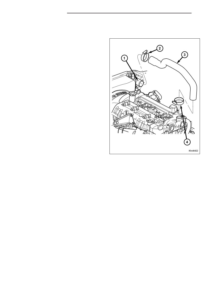
CHARGE AIR COOLER INLET HOSE
1. Open and support hood of vehicle.
2. Loosen hose clamps at both ends of charge air
cooler (CAC) inlet hose.
3. Remove CAC inlet hose (3) from turbocharger and
CAC.
11 - 14
EXHAUST SYSTEM
KJ