Jeep Liberty KJ. Manual - part 922


  Index      Jeep     Jeep Liberty KJ - service repair manual 2006 year


Search            


Content   ..  920  921  922  923   ..


Jeep Liberty KJ. Manual - part 922


INSTALLATION

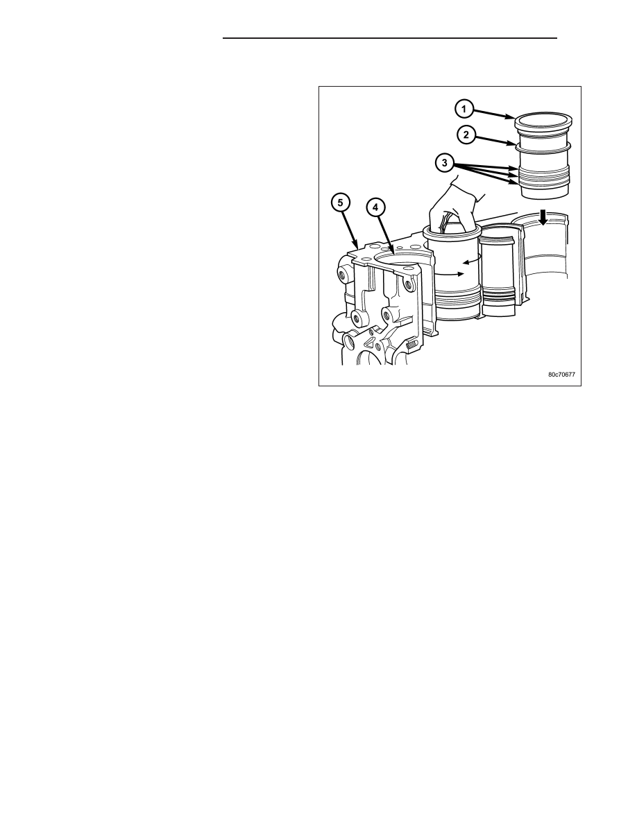
CAUTION: Cleanliness can not be over empha-
sized enough when cleaning the cylinder liner (1)
to engine block (5) mating surfaces. Failure to do
so will result in the wrong protrusion reading.
Only one shim (2) per sleeve fitting. DO NOT stack
or re-use shims (2).

NOTE: When installing cylinder liners (1) for pro-
trusion measurement, remove all O-rings (3) and
discard original shim (2).

1. Carefully clean cylinder liner (1) and engine block

(5), and degrease the engine block deck where it
comes into contact with the cylinder liners (1).
Install the cylinder liners in the engine block (5) as
shown, rotating them back and forth by 45° in order
to guarantee correct positioning.

NOTE: All Measurements Must Be Taken On the
High Pressure Pump Side.

2. Measure the cylinder liner (1)) recess relative to

block deck with dial indicator VM.1013 mounted on
a special tool VM.1010 A.. Zero dial gauge on
block deck.

NOTE: The cylinder liner (1) reading will actually be a negative number.

3. Move dial gauge to cylinder liner (1) edge record reading on dial gauge. The reading should be negative.

4. Remove cylinder liner (1) and special tools.

5. Then select the correct shim (2) thickness to give proper protrusion (0.00 - 0.05 mm).

NOTE: The O-rings (3) are used toward the bottom of the cylinder liner (1). Each cylinder liner (1) has three
O-rings (3) that prevent coolant and engine oil from mixing. The brown (bottom) O-ring (3) is an oil seal and
the two black (top) O-rings (3) are water seals.

6. Fit the proper shim (2), and the O-rings (3), onto the cylinder liner (1).

7. Lubricate the lower cylinder liner (1) location in the engine block (5).

CAUTION: When installing special tool VM.1076, make sure the tool does not rotate when tightening and
damage the cylinder liner (1). DO NOT rotate the engine with out special tool VM.1076 in position.

8. Fit the cylinder liners in the crankcase making sure that the shim (2) is positioned correctly in the seat. Lock the

cylinder liners (1) in position using special tool (VM.1076) and bolts tightened to 50 N·m (37 ft.lbs.).

9 - 1646

ENGINE - 2.8L DIESEL

KJ

NOTE: After measuring cylinder liner (1) protru-
sion again, piston protrusion must be measured to
prevent the wrong cylinder head gasket selection.

9. Measure cylinder liner (1) protrusion again. It

should be 0.00 - 0.05 mm.

10. Reassemble engine.

11. Install engine in vehicle.

KJ

ENGINE - 2.8L DIESEL

9 - 1647

ROD-PISTON AND CONNECTING

DESCRIPTION

The pistons (2) are of a free floating design. Oil jets in
the engine block lubricate and cool the piston and pis-
ton pin (1) assembly. The connecting rods (7) have a
pressed in place wrist pin bushing which is lubricated
by the oil jets. Connecting rod (7) and bearing caps
have cracked mating surfaces and are not inter-
changeable..

STANDARD PROCEDURE - PISTON RING FITTING

1. Wipe cylinder bore clean. Insert ring and push

down with piston to ensure it is square in bore. The
ring gap measurement must be made with the ring
positioning at least 12 mm (0.50 in.) from bottom of
cylinder bore. Check gap with feeler gauge. Top
compression ring gap .30 to .45mm (.0118 to .0177
in.). Second compression ring gap .30 to .45mm
(.0118 to .0177 in.). Oil control ring gap .25 to
.50mm (.0098 to .0196 in.).

2. If ring gaps exceed dimension given, new rings or

cylinder liners must be fitted. Keep piston rings in
piston sets.

9 - 1648

ENGINE - 2.8L DIESEL

KJ

3. Check piston ring to groove clearance. Top com-

pression ring gap .080 to .130mm (.0031 to .0051
in.). Second compression ring gap .070 to .110mm
(.0027 to .0043 in.). Oil control ring gap .040 to
.080mm (.0015 to .0031 in.).

REMOVAL

NOTE: Both the connecting rod and the connecting rod cap are paint marked to aid during assembly. Paint
marks disappear after time. If the rod and the cap are not marked with paint, paint mark or scribe them
before disassembly.

1. Disconnect negative battery cable.

2. Remove cylinder head (Refer to 9 - ENGINE/CYLINDER HEAD - REMOVAL).

3. Raise vehicle on hoist.

4. Remove oil pan (Refer to 9 - ENGINE/LUBRICATION/OIL PAN - REMOVAL).

5. Remove oil pump pickup tube. (Refer to 9 - ENGINE/LUBRICATION/OIL PUMP - REMOVAL).

6. Remove balance shaft assembly (Refer to 9 - ENGINE/VALVE TIMING/BALANCE SHAFT - REMOVAL).

7. Remove top ridge of cylinder bores with a ridge reamer before removing pistons from cylinder block. Be sure to

keep top of pistons covered during this operation.

8. Piston and connecting rods must be removed from top of cylinder block. Rotate crankshaft so that each con-

necting rod is centered in cylinder bore.

NOTE: Be careful not to nick or scratch crankshaft journals

9. After removal, install bearing cap on the mating rod and mark pistons with matching cylinder number when

removed from engine block.

KJ

ENGINE - 2.8L DIESEL

9 - 1649


Content   ..  920  921  922  923   ..