Jeep Liberty KJ. Manual - part 880


  Index      Jeep     Jeep Liberty KJ - service repair manual 2006 year


Search            


Content   ..  878  879  880  881   ..


Jeep Liberty KJ. Manual - part 880


INSTALLATION

INSTALLATION LEFT CYLINDER HEAD

NOTE: The cylinder head bolts are tightened using
a torque plus angle procedure. The bolts must be
examined

BEFORE

reuse.

If

the

threads

are

necked down the bolts should be replaced.

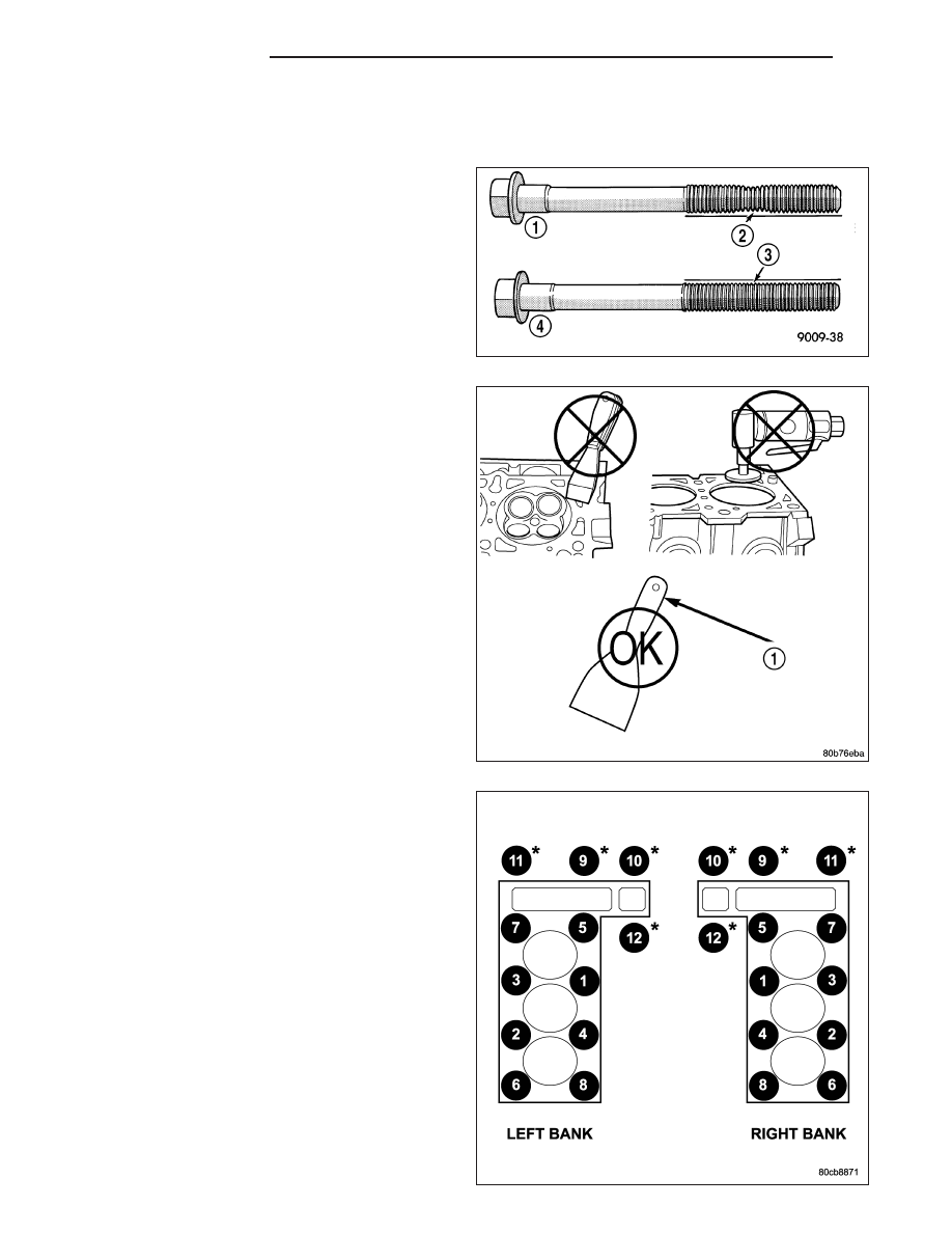
Necking can be checked by holding a straight edge
against the threads. If all the threads do not contact
the scale (1), the bolt should be replaced.

CAUTION: When cleaning cylinder head and cylin-
der block surfaces, DO NOT use a metal scraper
because the surfaces could be cut or ground. Use
only a wooden or plastic scraper.

1. Clean the cylinder head and cylinder block mating

surfaces.

2. Position the new cylinder head gasket on the locat-

ing dowels.

CAUTION: When installing cylinder head, use care
not damage the tensioner arm or the guide arm.

3. Position the cylinder head onto the cylinder block.

Make sure the cylinder head seats fully over the
locating dowels.

NOTE: The four smaller cylinder head mounting
bolts require sealant to be added to them before
installing. Failure to do so may cause leaks.

4. Lubricate the cylinder head bolt threads with clean

engine oil and install the eight M11 bolts.

5. Coat the four M8 cylinder head bolts with Mopar

T

Lock and Seal Adhesive then install the bolts.

NOTE: The cylinder head bolts are tightened using
an angle torque procedure, however, the bolts are
not a torque-to-yield design.

6. Tighten the bolts in sequence using the following

steps and torque values:

Step 1: Tighten bolts 1–8, 27 N·m (20 ft. lbs.).

Step 2: Verify that bolts 1–8, all reached 27 N·m
(20 ft. lbs.), by repeating step-1 without loosen-
ing the bolts. Tighten bolts 9 thru 12 to 14 N·m
(10 ft. lbs.).

Step 3: Tighten bolts 1–8, 90 degrees.

9 - 1478

ENGINE - 3.7L

KJ

Step 4: Tighten bolts 1–8, 90 degrees, again. Tighten bolts 9–12, 26 N·m (19 ft. lbs.)

7. Position the secondary chain onto the camshaft drive gear, making sure one marked chain link is on either side

of the V6 mark on the gear then using Special Tool 8428 Camshaft Wrench, position the gear onto the camshaft.

CAUTION: Remove excess oil from camshaft sprocket retaining bolt before reinstalling bolt. Failure to do so
may cause over-torqueing of bolt resulting in bolt failure.

8. Install the camshaft drive gear retaining bolt.

9. Install the left side secondary chain guide.

10. Install the cylinder head access plug.

11. Re-set and Install the left side secondary chain tensioner.

12. Remove Special Tool 8429.

13. Install the timing chain cover.

14. Install the crankshaft damper. Tighten damper bolt 175 N·m (130 Ft. Lbs.).

15. Install the power steering pump.

16. Install the fan blade assembly and fan shroud.

17. Install the cylinder head cover.

18. Install the intake manifold.

19. Refill the cooling system

20. Raise the vehicle.

21. Install the exhaust pipe onto the left exhaust manifold.

22. Lower the vehicle.

23. Connect the negative cable to the battery.

24. Start the engine and check for leaks.

KJ

ENGINE - 3.7L

9 - 1479

CAMSHAFT

DESCRIPTION

The camshafts consist of powdered metal steel lobes which are sinter-bonded to a steel tube. Four bearing journals
are machined into the camshaft. Camshaft end play is controlled by two thrust walls that border the nose piece
journal.

REMOVAL

CAUTION: When the timing chain is removed and the cylinder heads are still installed, DO NOT forcefully
rotate the camshafts or crankshaft independently of each other. Severe valve and/or piston damage can
occur.

CAUTION: When removing the cam sprocket, timing chains or camshaft, Failure to use Special Tool 8379
will result in hydraulic tensioner ratchet over extension, requiring timing chain cover removal to reset the
tensioner ratchet.

1. Remove cylinder head cover (Refer to 9 - ENGINE/CYLINDER HEAD/CYLINDER HEAD COVER(S) -

REMOVAL).

2. Set engine to TDC cylinder #1, camshaft sprocket

V6 marks at the 12 o’clock position.

3. Mark one link on the secondary timing chain on

both sides of the V6 mark on the camshaft
sprocket to aid in installation.

CAUTION: Do not hold or pry on the camshaft tar-
get wheel (Located on the right side camshaft
sprocket) for any reason, Severe damage will
occur to the target wheel resulting in a vehicle no
start condition.

4. Loosen but DO NOT remove the camshaft sprocket

retaining bolt. Leave the bolt snug against the
sprocket.

NOTE: The timing chain tensioners must be
secured prior to removing the camshaft sprockets.
Failure to secure tensioners will allow the tension-
ers

to

extend,

requiring

timing

chain

cover

removal in order to reset tensioners.

CAUTION: Do not force wedge past the narrowest point between the chain strands. Damage to the tension-
ers may occur.

5. Position Special Tool 8379 timing chain wedge between the timing chain strands, tap the tool to securely wedge

the timing chain against the tensioner arm and guide.

9 - 1480

ENGINE - 3.7L

KJ

6. Hold the camshaft with Special Tool 8428 Camshaft

Wrench , while removing the camshaft sprocket
bolt and sprocket.

7. Using Special Tool 8428 Camshaft Wrench, gently

allow the camshaft to rotate 5° clockwise until the
camshaft is in the neutral position (no valve load).

8. Starting at the outside working inward, loosen the

camshaft bearing cap retaining bolts 1/2 turn at a
time. Repeat until all load is off the bearing caps.

CAUTION: DO NOT STAMP OR STRIKE THE CAM-
SHAFT BEARING CAPS. SEVERE DAMAGE WILL
OCCUR TO THE BEARING CAPS.

NOTE: When the camshaft is removed the rocker
arms may slide downward, mark the rocker arms
before removing camshaft.

9. Remove the camshaft bearing caps and the

camshaft.

INSTALLATION

1. Lubricate camshaft journals with clean engine oil.

NOTE: Position the left side camshaft so that the
camshaft sprocket dowel is near the 1 o’clock
position, This will place the camshaft at the neu-
tral position easing the installation of the camshaft
bearing caps.

2. Position the camshaft into the cylinder head.

3. Install the camshaft bearing caps, hand tighten the

retaining bolts.

NOTE: Caps should be installed so that the
stamped numbers on the caps are in numerical
order, ( 1 thru 4 ) from the front to the rear of the
engine. All caps should be installed so that the
stamped arrows on the caps point toward the front
of the engine.

4. Working in 1/2 turn increments, tighten the bearing

cap retaining bolts starting with the middle cap
working outward.

5. Torque the camshaft bearing cap retaining bolts to

11 N·m (100 in. lbs.) .

6. Position the camshaft drive gear into the timing chain aligning the V6 mark between the two marked chain links

(Two links marked during removal).

7. Using Special Tool 8428 Camshaft Wrench, rotate the camshaft until the camshaft sprocket dowel is aligned with

the slot in the camshaft sprocket. Install the sprocket onto the camshaft.

CAUTION: Remove excess oil from camshaft sprocket bolt. Failure to do so can cause bolt over-torque
resulting in bolt failure.

8. Remove excess oil from bolt, then install the camshaft sprocket retaining bolt and hand tighten.

9. Remove Special Tool 8379 timing chain wedge.

KJ

ENGINE - 3.7L

9 - 1481


Content   ..  878  879  880  881   ..