Jeep Liberty KJ. Manual - part 855


  Index      Jeep     Jeep Liberty KJ - service repair manual 2006 year


Search            


Content   ..  853  854  855  856   ..


Jeep Liberty KJ. Manual - part 855


13.

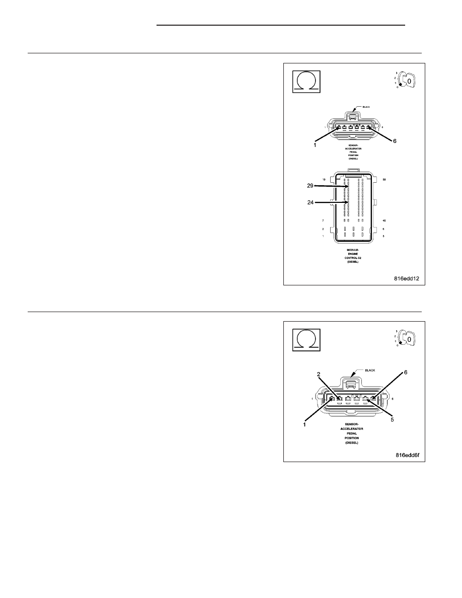
APP SENSOR 5-VOLT SUPPLY CIRCUITS OPEN

Turn the ignition off.

Disconnect the APP Sensor harness connector.

Disconnect the ECM harness connectors.

Measure the resistance of the Accelerator Pedal Position Sensor 5-volt
Supply circuit.

Is the resistance below 10.0 ohms?

Yes

>> Go To 14

No

>> Repair the Accelerator Pedal Position Sensor 5-Volt Supply

circuit for an open.

Perform ROAD TEST VERIFICATION - VER-2.

14.

APP SENSOR 5-VOLT SUPPLY CIRCUIT SHORTED TO SENSOR GROUND

Turn the ignition off.

Disconnect the APP Sensor harness connector.

Disconnect the ECM harness connectors.

Measure the resistance between the Accelerator Pedal Position Sensor
5-Volt Supply circuit and both Sensor Ground circuits in the APP Sensor
harness connector.

Is the resistance above 1000 ohms?

Yes

>> Go To 15

No

>> Repair the 5-Volt Supply circuit for a short to the Sensor

Ground circuit.

Perform ROAD TEST VERIFICATION - VER-2.

9 - 1378

ENGINE DIESEL DIAG

KJ

15.

APP SENSOR 5-VOLT SUPPLY CIRCUIT SHORTED TO GROUND

Turn the ignition off.

Disconnect the APP Sensor harness connector.

Disconnect the ECM harness connectors.

Measure the resistance between ground and the Accelerator Pedal
Position Sensor 5-volt Supply circuit.

Is the resistance below 1000 ohms?

Yes

>> Repair the Accelerator Pedal Position Sensor 5-Volt Supply

circuit for a short to ground.

Perform ROAD TEST VERIFICATION - VER-2.

No

>> Go To 16

16.

APP SENSOR 5-VOLT SUPPLY SHORTED TO VOLTAGE

Turn the ignition off.

Disconnect the APP Sensor harness connector.

Disconnect the ECM harness connectors.

Remove the ASD Relay.

Connect a jumper wire between cavity 30 and cavity 87 of the ASD
Relay connector.

Turn the ignition on.

Measure the voltage of the Accelerator Pedal Position Sensor 5-Volt
Supply circuit in the ECM harness connector.

Is the voltage above 1.0 volt?

Yes

>> Repair the Accelerator Pedal Position Sensor 5-Volt Supply

circuit for a short to voltage.

Perform the ECM Verification Test Ver. 1 (Refer to 9 -
ENGINE - DIAGNOSIS AND TESTING).

No

>> Replace and program the Engine Control Module in accor-

dance with the Service Information.

Perform the ECM Verification Test Ver. 1 (Refer to 9 -
ENGINE - DIAGNOSIS AND TESTING).

KJ

ENGINE DIESEL DIAG

9 - 1379

P2125-ACC PEDAL POSITION SENSOR 2 SIGNAL VOLTAGE TOO HIGH

For a complete wiring diagram Refer to Section 8W

9 - 1380

ENGINE DIESEL DIAG

KJ

When Monitored:
With the ignition on.

Set Condition:
The APP Sensor #2 Signal circuit voltage is above 2.5 volts for 0.3 second.

Possible Causes

ACCELERATOR PEDAL POSITION SENSOR

ECM - APP SENSOR 1 5-VOLT SUPPLY CIRCUIT

SENSOR GROUND OPEN (APP SENSOR)

INTERMITTENT CONDITION

APP SENSOR 5-VOLT SUPPLY CIRCUIT OPEN

APP SENSOR SIGNAL CIRCUIT OPEN

APP SENSOR 5-VOLT SUPPLY CIRCUIT SHORTED TO SENSOR GROUND

APP SENSOR SIGNAL CIRCUIT SHORTED TO GROUND

APP SENSOR 5-VOLT SUPPLY CIRCUIT SHORTED TO GROUND

VERIFY APP SENSOR OPERATION

APP SENSOR SIGNAL CIRCUIT SHORTED TO THE SENSOR GROUND CIRCUIT

APP SENSOR 5-VOLT SUPPLY CIRCUIT SHORTED TO VOLTAGE

ECM - SENSOR GROUND OPEN

APP SENSOR CIRCUIT SHORTED TO VOLTAGE

APP SENSOR GROUND CIRCUIT SHORTED TO VOLTAGE

ECM - APP SENSOR SIGNAL CIRCUIT

Diagnostic Test

1.

APP SENSOR IDLE VOLTAGE

NOTE: If DTC P0641, P0651 or P0697 is present with this DTC,
diagnose DTCs P0641, P0651 or P0697 before diagnosing this DTC.

NOTE: If the ECM detects and stores a DTC, the ECM also stores
the engine/vehicle operating conditions under which the DTC was
set. Some of these conditions are displayed on the scan tool at the
same time the DTC is displayed.

NOTE: Before erasing stored DTCs, record these conditions.
Attempting to duplicate these conditions may assist when check-
ing for an active DTC.

NOTE: The APP Sensor is a device that contains 2 separate poten-
tiometer type sensors. Each sensor has its own 5-volt supply cir-
cuit, sensor ground circuit and signal circuit. The APP Sensor no
longer incorporates a low-idle switch.

NOTE: The APP Sensor 2 signal should always be approximately
1/2 the voltage of the APP Sensor 1 signal.
Inspect the APP Sensor for proper travel from the rest position to the
fully depressed position.

Turn the ignition on.

Using a voltmeter, backprobe the APP Sensor 1 and APP Sensor 2 Signal circuits at the APP Sensor harness con-
nector with the accelerator pedal in the at rest position.

Is the voltage between 0.42 and 0.51 volt for sensor 1 and 0.19 and 0.28 volt for sensor 2?

Yes

>> Go To 2

No

>> Go To 4

KJ

ENGINE DIESEL DIAG

9 - 1381


Content   ..  853  854  855  856   ..