Jeep Liberty KJ. Manual - part 853
15.
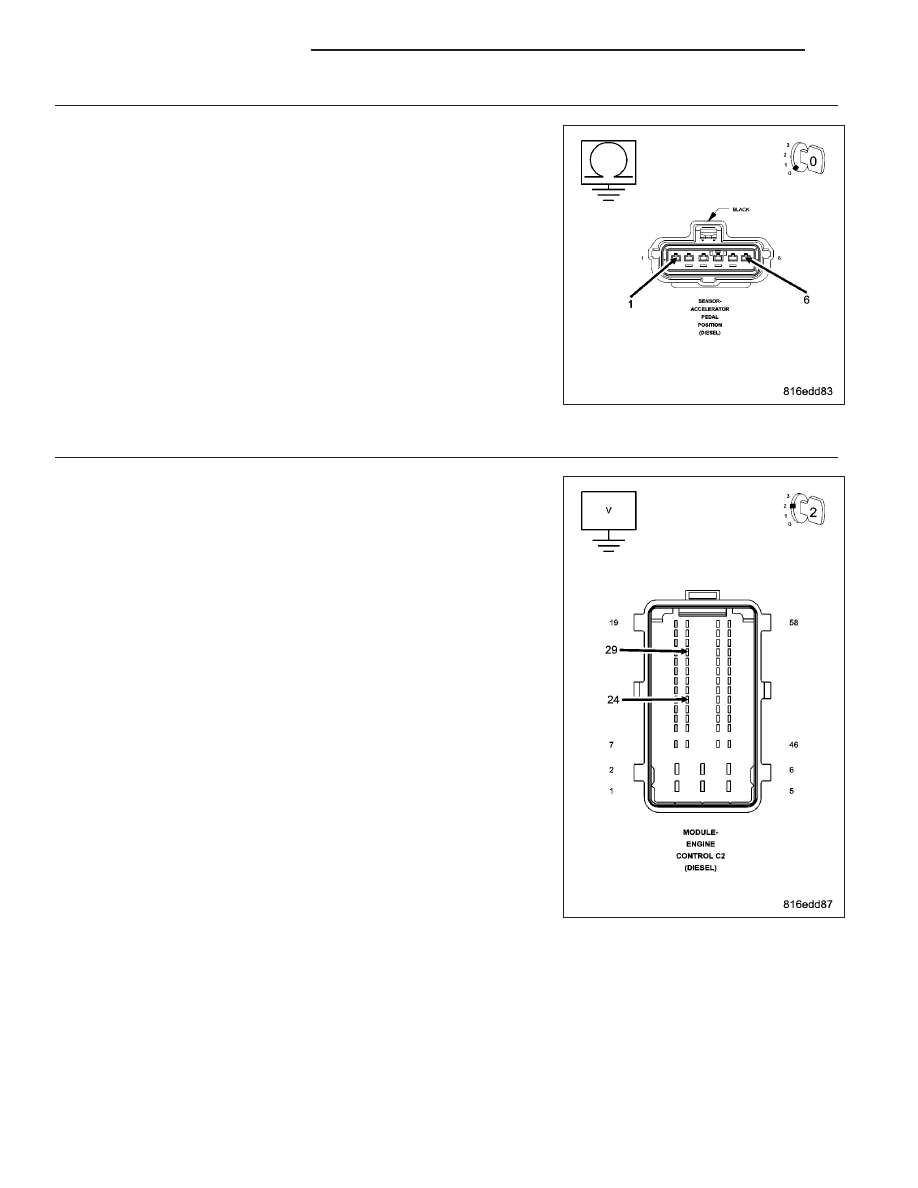
APP SENSOR 5-VOLT SUPPLY CIRCUIT SHORTED TO GROUND
Turn the ignition off.
Disconnect the APP Sensor harness connector.
Disconnect the ECM harness connectors.
Measure the resistance between ground and the Accelerator Pedal
Position Sensor 5-volt Supply circuit.
Is the resistance below 1000 ohms?
Yes
>> Repair the Accelerator Pedal Position Sensor 5-Volt Supply
circuit for a short to ground.
Perform ROAD TEST VERIFICATION - VER-2.
No
>> Go To 16
16.
APP SENSOR 5-VOLT SUPPLY SHORTED TO VOLTAGE
Turn the ignition off.
Disconnect the APP Sensor harness connector.
Disconnect the ECM harness connectors.
Remove the ASD Relay.
Connect a jumper wire between cavity 30 and cavity 87 of the ASD
Relay connector.
Turn the ignition on.
Measure the voltage of the Accelerator Pedal Position Sensor 5-Volt
Supply circuit in the ECM harness connector.
Is the voltage above 1.0 volt?
Yes
>> Repair the Accelerator Pedal Position Sensor 5-Volt Supply
circuit for a short to voltage.
Perform ROAD TEST VERIFICATION - VER-2.
No
>> Replace and program the Engine Control Module in accor-
dance with the Service Information.
Perform the ECM Verification Test Ver. 1 (Refer to 9 -
ENGINE - DIAGNOSIS AND TESTING).
9 - 1370
ENGINE DIESEL DIAG
KJ