Jeep Liberty KJ. Manual - part 758
2.
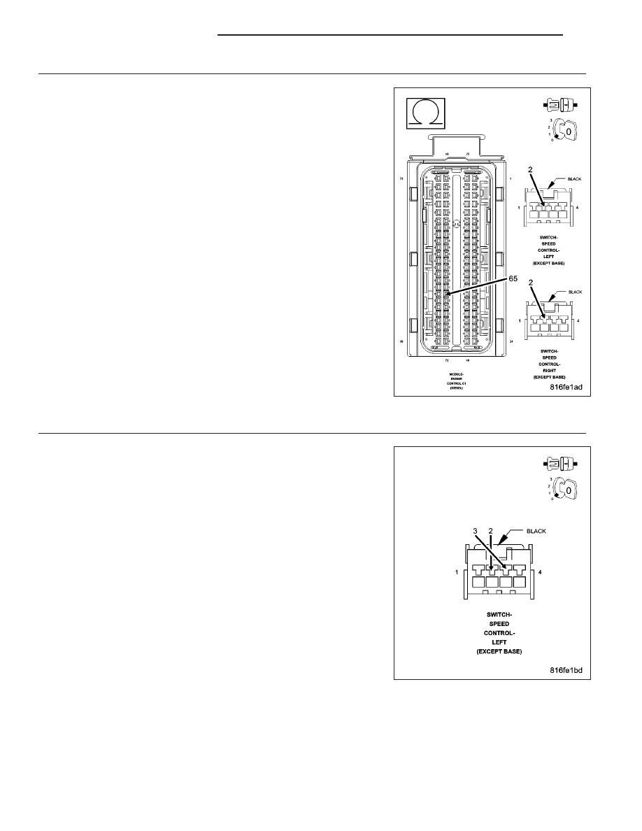
SENSOR GROUND OPEN
Turn the ignition off.
Disconnect both S/C Switch harness connectors.
Disconnect the ECM harness connectors.
Measure the resistance of the Sensor Ground circuit between each S/C
Switch harness connector and the ECM harness connector.
Is the resistance below 10.0 ohms for each measurement?
Yes
>> Go To 3
No
>> Repair the Sensor Ground circuit for an open.
Perform the ECM Verification Test Ver. 1 (Refer to 9 -
ENGINE - DIAGNOSIS AND TESTING).
3.
ECM - SENSOR GROUND OPEN
Turn the ignition off.
Disconnect one of the S/C Switch harness connectors.
With the scan tool, read the S/C Switch Voltage.
While monitoring the scan tool, connect a jumper wire between the S/C
Switch #2 Signal circuit and the Sensor Ground circuit in the S/C Switch
harness connector.
Does the scan tool display below 0.1 volt with the jumper wire
connected?
Yes
>> Replace the Speed Control Switches.
Perform the ECM Verification Test Ver. 1 (Refer to 9 -
ENGINE - DIAGNOSIS AND TESTING).
No
>> Replace and program the Engine Control Module in accor-
dance with the Service Information.
Perform the ECM Verification Test Ver. 1 (Refer to 9 -
ENGINE - DIAGNOSIS AND TESTING).
9 - 1090
ENGINE DIESEL DIAG
KJ