Jeep Liberty KJ. Manual - part 756


  Index      Jeep     Jeep Liberty KJ - service repair manual 2006 year


Search            


Content   ..  754  755  756  757   ..


Jeep Liberty KJ. Manual - part 756


6.

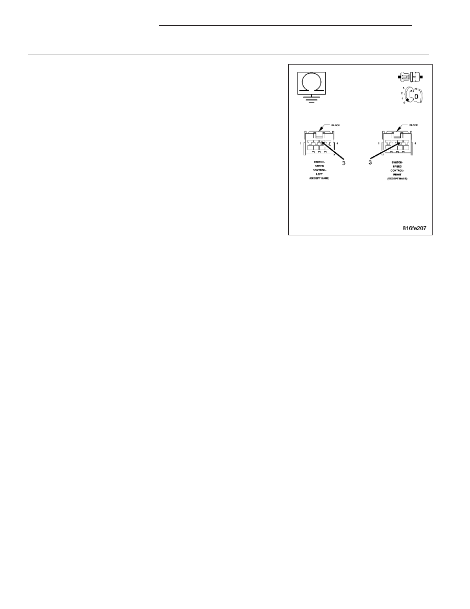
S/C SWITCH #2 SIGNAL CIRCUIT SHORTED TO VOLTAGE

Turn the ignition off.

Disconnect both S/C Switch harness connectors.

Disconnect the ECM harness connectors.

Remove the ASD Relay from the PDC.

Connect a jumper wire between cavity 30 and cavity 87 of the ASD
Relay connector.

Turn the ignition on.

Measure the voltage of the S/C Switch #2 Signal circuit.

Is the voltage above 1.0 volt?

Yes

>> Repair the S/C Switch #2 Signal circuit for a short to volt-

age.

Perform the ECM Verification Test Ver. 1 (Refer to 9 -
ENGINE - DIAGNOSIS AND TESTING).

No

>> Replace and program the Engine Control Module in accor-

dance with the Service Information.

Perform the ECM Verification Test Ver. 1 (Refer to 9 -
ENGINE - DIAGNOSIS AND TESTING).

9 - 1082

ENGINE DIESEL DIAG

KJ

P0589-S/C SWITCH #2 SIGNAL CIRCUIT VOLTAGE TOO LOW

For a complete wiring diagram Refer to Section 8W

KJ

ENGINE DIESEL DIAG

9 - 1083

When Monitored:
With the ignition on.

Set Condition:
The S/C Switch #2 Signal is below 0.60 volt for 1.0 second.

Possible Causes

ECM - S/C SIGNAL CIRCUIT OPEN

ECM - S/C SIGNAL CIRCUIT SHORTED TO VOLTAGE

ECM - SENSOR GROUND OPEN

S/C SWITCH SIGNAL CIRCUIT OPEN

S/C SWITCH SIGNAL CIRCUIT OPEN

S/C SWITCH SIGNAL CIRCUIT SHORT TO GROUND

S/C SWITCH SIGNAL CIRCUIT SHORTED TO VOLTAGE

S/C SWITCH SIGNAL CIRCUIT SHORTED TO VOLTAGE

SENSOR GROUND OPEN

SPEED CONTROL SWITCHES

Diagnostic Test

1.

VERIFY S/C SWITCH SIGNAL CIRCUIT VOLTAGE

NOTE: If the ECM detects and stores a DTC, the ECM also stores
the engine/vehicle operating conditions under which the DTC was
set. Some of these conditions are displayed on the DRB at the
same time the DTC is displayed.

NOTE: Before erasing stored DTCs, record these conditions.
Attempting to duplicate these conditions may assist when check-
ing for an active DTC.
Turn the ignition off.

Disconnect the harness connectors from both S/C Switches.

Turn the ignition on.

Measure the voltage of the S/C Switch #2 Signal circuit at both S/C
Switch harness connectors.

Select the appropriate voltage reading.

4.5 to 5.5 volts at both connectors.

Go To 2

4.5 to 5.5 volts at only one connector.

Repair the S/C Switch Signal circuit that measured below
4.5 volts for an open.

Perform the ECM Verification Test Ver. 1 (Refer to 9 - ENGINE - DIAGNOSIS AND TESTING).

Below 4.5 volts at both connectors.

Go To 4

Above 5.5 volts for either measurement.

Go To 6

9 - 1084

ENGINE DIESEL DIAG

KJ

2.

SENSOR GROUND OPEN

Turn the ignition off.

Disconnect both S/C Switch harness connectors.

Disconnect the ECM harness connectors.

Measure the resistance of the Sensor Ground circuit between each S/C
Switch harness connector and the ECM harness connector.

Is the resistance below 10.0 ohms for each measurement?

Yes

>> Go To 3

No

>> Repair the Sensor Ground circuit for an open.

Perform the ECM Verification Test Ver. 1 (Refer to 9 -
ENGINE - DIAGNOSIS AND TESTING).

3.

ECM - SENSOR GROUND OPEN

Turn the ignition off.

Disconnect one of the S/C Switch harness connectors.

With the scan tool, read the S/C Switch Voltage.

While monitoring the scan tool, connect a jumper wire between the S/C
Switch #2 Signal circuit and the Sensor Ground circuit in the S/C Switch
harness connector.

Does the scan tool display below 0.1 volt with the jumper wire
connected?

Yes

>> Replace the Speed Control Switches.

Perform the ECM Verification Test Ver. 1 (Refer to 9 -
ENGINE - DIAGNOSIS AND TESTING).

No

>> Replace and program the Engine Control Module in accor-

dance with the Service Information.

Perform the ECM Verification Test Ver. 1 (Refer to 9 -
ENGINE - DIAGNOSIS AND TESTING).

KJ

ENGINE DIESEL DIAG

9 - 1085


Content   ..  754  755  756  757   ..