Jeep Liberty KJ. Manual - part 754
•
When Monitored:
With the ignition switch on and no other S/C Switch DTC’s present.
•
Set Condition:
The S/C Switch #2 signal voltage is not within a valid switch signal range.
Possible Causes
ECM - S/C SIGNAL CIRCUIT OPEN
ECM - S/C SIGNAL CIRCUIT SHORTED TO VOLTAGE
ECM - SENSOR GROUND OPEN
S/C SWITCH SIGNAL CIRCUIT OPEN
S/C SWITCH SIGNAL CIRCUIT OPEN
S/C SWITCH SIGNAL CIRCUIT SHORT TO GROUND
S/C SWITCH SIGNAL CIRCUIT SHORTED TO VOLTAGE
S/C SWITCH SIGNAL CIRCUIT SHORTED TO VOLTAGE
SENSOR GROUND OPEN
SPEED CONTROL SWITCHES
Diagnostic Test
1.
VERIFY S/C SWITCH SIGNAL CIRCUIT VOLTAGE
NOTE: If the ECM detects and stores a DTC, the ECM also stores
the engine/vehicle operating conditions under which the DTC was
set. Some of these conditions are displayed on the scan tool at the
same time the DTC is displayed.
NOTE: Before erasing stored DTCs, record these conditions.
Attempting to duplicate these conditions may assist when check-
ing for an active DTC.
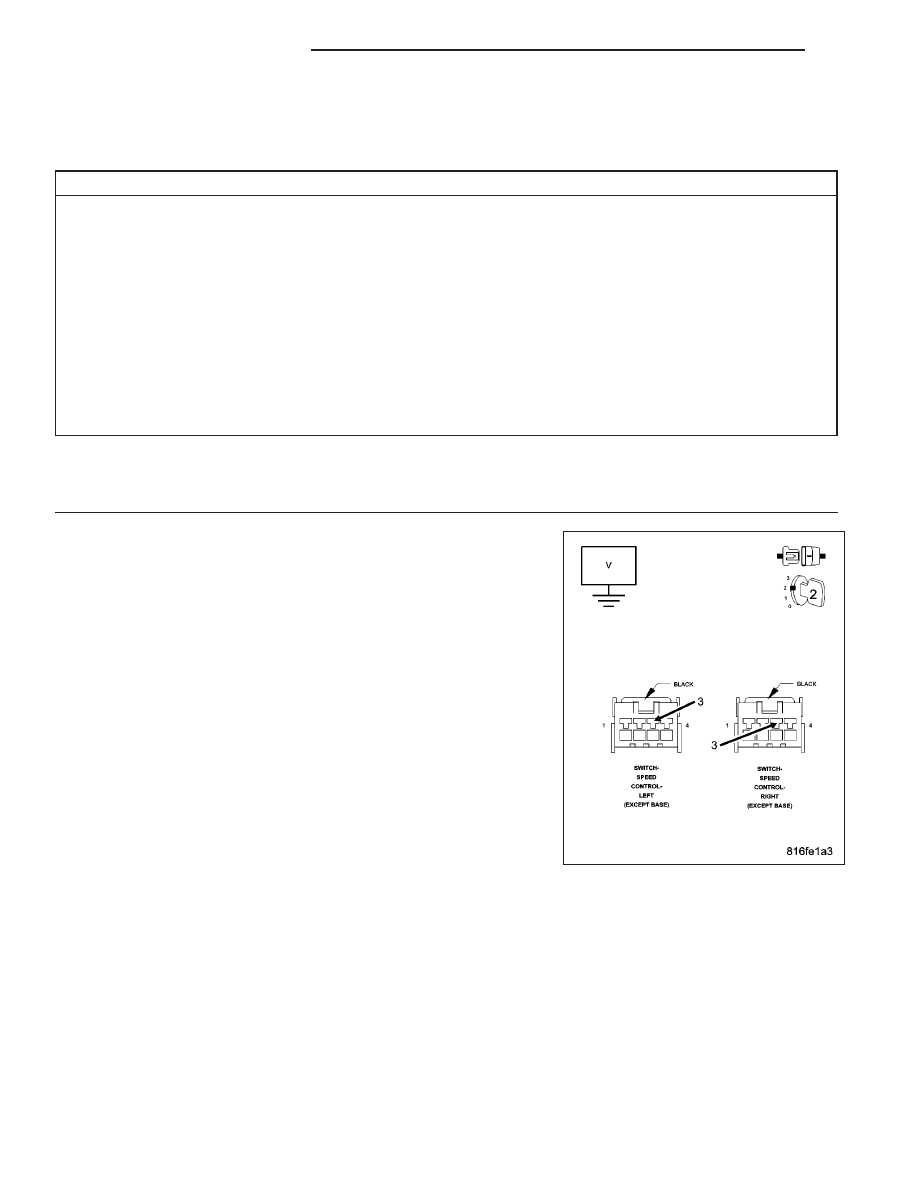
Turn the ignition off.
Disconnect the harness connectors from both S/C Switches.
Turn the ignition on.
Measure the voltage of the S/C Switch #2 Signal circuit at both S/C
Switch harness connectors.
Select the appropriate voltage reading.
4.5 to 5.5 volts at both connectors.
Go To 2
4.5 to 5.5 volts at only one connector.
Repair the S/C Switch Signal circuit that measured below
4.5 volts for an open.
Perform the ECM Verification Test Ver. 1 (Refer to 9 - ENGINE - DIAGNOSIS AND TESTING).
Below 4.5 volts at both connectors.
Go To 4
Above 5.5 volts for either measurement.
Go To 6
9 - 1074
ENGINE DIESEL DIAG
KJ