Jeep Liberty KJ. Manual - part 602
•
When Monitored:
With the ignition key on. The speed control switched on and the brake pedal is not pressed.
•
Set Condition:
The speed control power supply circuit is either open or shorted to ground for more than 2.6 seconds. One
Trip Fault. Three good trips to turn off the MIL.
Possible Causes
(V32) S/C SUPPLY CIRCUIT OPEN
(V32) S/C SUPPLY CIRCUIT SHORTED TO GROUND
(V30) S/C BRAKE SWITCH OUTPUT CIRCUIT OPEN
(V30) S/C BRAKE SWITCH OUTPUT CIRCUIT SHORTED TO GROUND
STOP LAMP SWITCH
PCM
Always perform the Pre-Diagnostic Troubleshooting procedure before proceeding. (Refer to 9 - ENGINE -
DIAGNOSIS AND TESTING).
Diagnostic Test
1.
ACTIVE DTC
NOTE: If this code is setting on a vehicle that doesn’t have a S/C Servo, flash the correct code into the PCM
or the wrong PCM may have previously been installed.
Ignition on, engine not running.
With a scan tool, read DTCs.
Is the DTC active at this time?
Yes
>> Go To 2
No
>> Refer to the INTERMITTENT CONDITION Diagnostic Procedure.
Perform the POWERTRAIN VERIFICATION TEST. (Refer to 9 - ENGINE - STANDARD PROCEDURE)
2.
(V32) S/C SUPPLY CIRCUIT
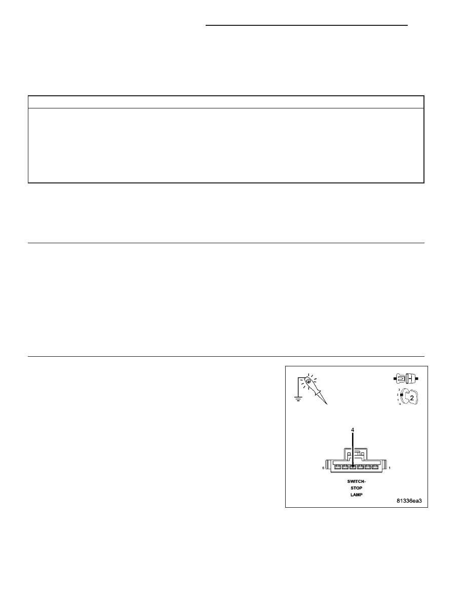
Turn the ignition off.
Disconnect the Stop Lamp Switch harness connector.
Using a 12-volt test light connected to ground, probe the (V32) S/C
Supply circuit in the Switch harness connector while holding the Cruise
Switch in the ON position.
Does the test light illuminate brightly?
Yes
>> Go To 3
No
>> Go To 7
9 - 466
ENGINE ELECTRICAL DIAGNOSTICS
KJ