Jeep Liberty KJ. Manual - part 573


  Index      Jeep     Jeep Liberty KJ - service repair manual 2006 year


Search            


Content   ..  571  572  573  574   ..


Jeep Liberty KJ. Manual - part 573


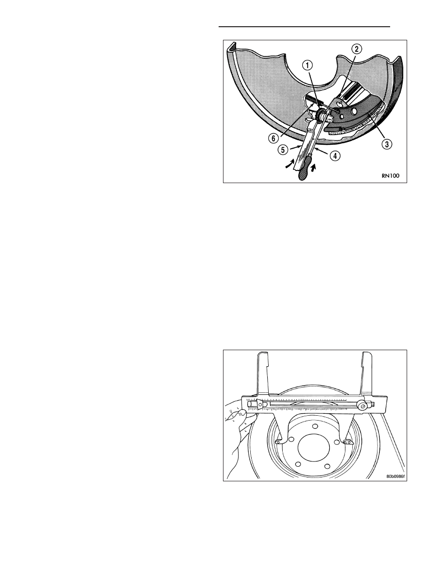
6. Rotate adjuster screw star wheel (move tool handle

upward) until slight drag can be felt when wheel is
rotated.

7. Push and hold adjuster lever away from star wheel

with thin screwdriver.

8. Back off adjuster screw star wheel until brake drag

is eliminated.

9. Repeat adjustment at opposite wheel. Be sure

adjustment is equal at both wheels.

10. Install support plate access hole plugs.

11. Adjust parking brake cable and lower vehicle.

12. Apply park brake hand lever and make sure park

brakes hold the vehicle staionary.

13. Release park brake hand lever.

REAR DRUM IN HAT PARK BRAKE
(ROTOR REMOVED)

Under normal circumstances, the only time adjustment is required is when the shoes are replaced, removed for
access to other parts, or when one or both rotors are replaced.

Adjustment can be made with a standard brake gauge or with adjusting tool. Adjustment is performed with the com-
plete brake assembly installed on the backing plate.

CAUTION: Before adjusting the park brake shoes be sure that the park brake pedal is in the fully released
position. If park brake pedal is not in the fully released position, the park brake shoes can not be accurately
adjusted.

1. Raise vehicle.

2. Remove tire and wheel.

3. Remove disc brake caliper from caliper adapter (Refer to 5 - BRAKES/HYDRAULIC/MECHANICAL/DISC BRAKE

CALIPERS - REMOVAL).

4. Remove rotor from the axleshaft (Refer to 5 - BRAKES/HYDRAULIC/MECHANICAL/ROTORS - REMOVAL).

NOTE: When measuring the brake drum diameter,
the diameter should be measured in the center of
the area in which the park brake shoes contact the
surface of the brake drum.

5 - 52

BRAKES - BASE - SERVICE INFORMATION

KJ

5. Using Brake Shoe Gauge, Special Tool C-3919 (1),

or equivalent, accurately measure the inside diam-
eter of the park brake drum portion of the rotor.

6. Using a ruler (2) that reads in 64th of an inch,

accurately read the measurement of the inside
diameter of the park brake drum from the special
tool.

7. Reduce the inside diameter measurement of the

brake drum that was taken using Special Tool
C-3919 (2) by 1/64 of an inch. Reset Gauge, Brake
Shoe, Special Tool C-3919 (2) or the equivalent
used, so that the outside measurement jaws are
set to the reduced measurement.

8. Place Gauge, Brake Shoe, Special Tool C-3919 (2)

, or equivalent over the park brake shoes. The spe-
cial tool must be located diagonally across at the
top of one shoe and bottom of opposite shoe (wid-
est point) of the park brake shoes.

9. Using the star wheel adjuster, adjust the park brake

shoes until the lining on the park brake shoes just
touches the jaws on the special tool.

10. Repeat step 8 above and measure shoes in both

directions.

11. Install brake rotor on the axleshaft (Refer to 5 - BRAKES/HYDRAULIC/MECHANICAL/ROTORS - INSTALLA-

TION).

12. Rotate rotor to verify that the park brake shoes are not dragging on the brake drum. If park brake shoes are

dragging, remove rotor and back off star wheel adjuster one notch and recheck for brake shoe drag against
drum. Continue with the previous step until brake shoes are not dragging on brake drum.

13. Install disc brake caliper on caliper adapter (Refer to 5 - BRAKES/HYDRAULIC/MECHANICAL/DISC BRAKE

CALIPERS - INSTALLATION).

14. Install wheel and tire.

15. Tighten the wheel mounting nuts in the proper sequence until all nuts are torqued to half the specified torque.

Then repeat the tightening sequence to the full specified torque of 129 N·m (95 ft. lbs.).

16. Lower vehicle.

CAUTION: Before moving vehicle, pump brake pedal several times to ensure the vehicle has a firm enough
pedal to stop the vehicle.

NOTE: After parking brake lining replacement, it is recommended that the parking brake system be condi-
tioned prior to use. This is done by making one stop from 25 mph on dry pavement or concrete using light
to moderate force on the parking brake hand lever.

17. Road test the vehicle to ensure proper function of the vehicle’s brake system.

KJ

BRAKES - BASE - SERVICE INFORMATION

5 - 53

BRAKES - ABS ELECTRICAL DIAGNOSTICS

TABLE OF CONTENTS

page

page

BRAKES - ABS ELECTRICAL DIAGNOSTICS

DIAGNOSIS AND TESTING

C100A–LEFT FRONT WHEEL SPEED

SENSOR CIRCUIT. . . . . . . . . . . . . . . . . . . . . . . . . . 57

C1011–LEFT FRONT WHEEL SPEED

SENSOR SIGNAL ERRATIC
PERFORMANCE. . . . . . . . . . . . . . . . . . . . . . . . . . . . 62

C1014–LEFT FRONT WHEEL SPEED

COMPARATIVE PERFORMANCE. . . . . . . . . . . . . 65

C1015–RIGHT FRONT WHEEL SPEED

SENSOR CIRCUIT. . . . . . . . . . . . . . . . . . . . . . . . . . 68

C101C–RIGHT FRONT WHEEL SPEED

SENSOR SIGNAL ERRATIC
PERFORMANCE. . . . . . . . . . . . . . . . . . . . . . . . . . . . 73

C101F–RIGHT FRONT WHEEL SPEED

COMPARATIVE PERFORMANCE. . . . . . . . . . . . . 76

C1020–LEFT REAR WHEEL SPEED

SENSOR CIRCUIT. . . . . . . . . . . . . . . . . . . . . . . . . . 79

C1027–LEFT REAR WHEEL SPEED

SENSOR SIGNAL ERRATIC
PERFORMANCE. . . . . . . . . . . . . . . . . . . . . . . . . . . . 84

C102A–LEFT REAR WHEEL SPEED

COMPARATIVE PERFORMANCE. . . . . . . . . . . . . 87

C102B–RIGHT REAR WHEEL SPEED

SENSOR CIRCUIT. . . . . . . . . . . . . . . . . . . . . . . . . . 90

C1032–RIGHT REAR WHEEL SPEED

SENSOR SIGNAL ERRATIC
PERFORMANCE. . . . . . . . . . . . . . . . . . . . . . . . . . . . 95

C1035–RIGHT REAR WHEEL SPEED

COMPARATIVE PERFORMANCE. . . . . . . . . . . . . 98

C1041–LEFT FRONT TONE WHEEL

PERFORMANCE.. . . . . . . . . . . . . . . . . . . . . . . . . . 101

C1042–RIGHT FRONT TONE WHEEL

PERFORMANCE.. . . . . . . . . . . . . . . . . . . . . . . . . . 102

C1043–LEFT REAR TONE WHEEL

PERFORMANCE.. . . . . . . . . . . . . . . . . . . . . . . . . . 103

C1044–RIGHT REAR TONE WHEEL

PERFORMANCE.. . . . . . . . . . . . . . . . . . . . . . . . . . 104

C1046–LEFT FRONT WHEEL PRESSURE

PHASE MONITORING. . . . . . . . . . . . . . . . . . . . . . 105

C1047–RIGHT FRONT WHEEL PRESSURE

PHASE MONITORING. . . . . . . . . . . . . . . . . . . . . . 110

C1048–LEFT REAR WHEEL PRESSURE

PHASE MONITORING. . . . . . . . . . . . . . . . . . . . . . 115

C1049–RIGHT REAR WHEEL PRESSURE

PHASE MONITORING. . . . . . . . . . . . . . . . . . . . . . 120

C1073–ABS PUMP MOTOR CONTROL

CIRCUIT. . . . . . . . . . . . . . . . . . . . . . . . . . . . . . . . . . 125

C1078–TIRE REVOLUTIONS RANGE

PERFORMANCE.. . . . . . . . . . . . . . . . . . . . . . . . . . 127

C107C–BRAKE PEDAL SWITCH 1/2 STUCK . . 128

C107D–BRAKE PEDAL SWITCH 1/2

CORRELATION. . . . . . . . . . . . . . . . . . . . . . . . . . . . 131

C1210–G SENSOR INPUT CIRCUIT

PERFORMANCE.. . . . . . . . . . . . . . . . . . . . . . . . . . 135

C1219–STEERING ANGLE SENSOR

ERRATIC PERFORMANCE

. . . . . . . . . . . . . . . . . . 138

C121A–STEERING ANGLE SENSOR NOT

INITIALIZED. . . . . . . . . . . . . . . . . . . . . . . . . . . . . . . 142

C121C–TORQUE REQUEST SIGNAL

DENIED.. . . . . . . . . . . . . . . . . . . . . . . . . . . . . . . . . . 143

C121D–BRAKE PRESSURE SENSOR

CIRCUIT. . . . . . . . . . . . . . . . . . . . . . . . . . . . . . . . . . 145

C121E–BRAKE PRESSURE SENSOR

COMPARATIVE PERFORMANCE.. . . . . . . . . . . 146

C1231–DRIVE TEST: STEERING ANGLE

SENSOR. . . . . . . . . . . . . . . . . . . . . . . . . . . . . . . . . . 147

C1232–DRIVE TEST: PRESSURE SENSOR . . 151
C1234–DRIVE TEST: SENSOR CLUSTER

INSTALLATION. . . . . . . . . . . . . . . . . . . . . . . . . . . . 152

C1238-DRIVE TEST: UNSUCCESSFUL . . . . . . 154
C1239–EMISSIONS ROLLS TEST ACTIVE . . . 154
C123A–ESP SYSTEM SENSORS

CALIBRATION. . . . . . . . . . . . . . . . . . . . . . . . . . . . . 155

C123B–ESP SYSTEM CONTROL TOO LONG . 156
C123C–DYNAMICS SENSOR MOUNTING/

INSTALLATION PERFORMANCE. . . . . . . . . . . . 159

C123F–STEERING ANGLE SENSOR

COMPARATIVE PERFORMANCE.. . . . . . . . . . . 162

C1240–STEERING ANGLE SENSOR

OVERTRAVEL PERFORMANCE. . . . . . . . . . . . . 167

C1242–GSENSOR INPUT SIGNAL

PERFORMANCE.. . . . . . . . . . . . . . . . . . . . . . . . . . 172

C1243–G SENSOR NOT INITIALIZED . . . . . . . . 175
C2100–BATTERY VOLTAGE LOW . . . . . . . . . . . 177
C2101–BATTERY VOLTAGE HIGH . . . . . . . . . . . 180
C2111–SENSOR SUPPLY 1 VOLTAGE

CIRCUIT LOW. . . . . . . . . . . . . . . . . . . . . . . . . . . . . 183

C2112–SENSOR SUPPLY 1 VOLTAGE

CIRCUIT HIGH

. . . . . . . . . . . . . . . . . . . . . . . . . . . . . 184

C2114–DYNAMICS SENSOR SUPPLY

VOLTAGE LOW. . . . . . . . . . . . . . . . . . . . . . . . . . . . 185

C2115–DYNAMICS SENSOR SUPPLY

VOLTAGE HIGH

. . . . . . . . . . . . . . . . . . . . . . . . . . . . 189

C2116–ABS PUMP MOTOR SUPPLY LOW

VOLTAGE. . . . . . . . . . . . . . . . . . . . . . . . . . . . . . . . . 191

C2200–ANTI-LOCK BRAKE MODULE

INTERNAL

. . . . . . . . . . . . . . . . . . . . . . . . . . . . . . . . . 195

C2204–DYNAMICS SENSOR INTERNAL . . . . . 198
C2205–STEERING ANGLE SENSOR

INTERNAL

. . . . . . . . . . . . . . . . . . . . . . . . . . . . . . . . . 201

5 - 54

BRAKES - ABS ELECTRICAL DIAGNOSTICS

KJ

C2206–VEHICLE CONFIGURATION

MISMATCH.. . . . . . . . . . . . . . . . . . . . . . . . . . . . . . . 205

U0002–CAN C BUS OFF PERFORMANCE . . . 206
U0100–LOST COMMUNICATION WITH

ECM/PCM. . . . . . . . . . . . . . . . . . . . . . . . . . . . . . . . . 208

U0101–LOST COMMUNICATION WITH TCM . 210
U0125–LOST COMMUNICATION WITH

DYNAMICS SENSOR

. . . . . . . . . . . . . . . . . . . . . . . 212

U0126–LOST COMMUNICATION WITH

STEERING ANGLE SENSOR

. . . . . . . . . . . . . . . . 217

U0146–LOST COMMUNICATION WITH

CENTRAL GATEWAY.. . . . . . . . . . . . . . . . . . . . . . 219

U0401–IMPLAUSIBLE DATA RECEIVED

FROM ECM/PCM. . . . . . . . . . . . . . . . . . . . . . . . . . 221

U0429–IMPLAUSIBLE DATA RECEIVED

FROM SCM. . . . . . . . . . . . . . . . . . . . . . . . . . . . . . . 223

U1003–ESP CAN C BUS PERFORMANCE . . . 224
U1104–CAN C BUS CRC PERFORMANCE . . . 229
U140E–IMPLAUSIBLE VEHICLE

CONFIGURATION DATA RECEIVED. . . . . . . . . 234

U1501–IMPLAUSIBLE MESSAGE DATA

LENGTH RECEIVED FROM ECM/PCM

. . . . . . . 236

U1502–IMPLAUSIBLE MESSAGE DATA

LENGTH RECEIVED FROM TCM.. . . . . . . . . . . 238

U1503–IMPLAUSIBLE MESSAGE DATA

LENGTH RECEIVED FROM FCM / BCM

. . . . . . 240

ABS INTERMITTENT CONDITION . . . . . . . . . . . 242

STANDARD PROCEDURE

ABS VERIFICATION TEST — VER 1 . . . . . . . . . 243

KJ

BRAKES - ABS ELECTRICAL DIAGNOSTICS

5 - 55


Content   ..  571  572  573  574   ..