Jeep Liberty KJ. Manual - part 540
12.
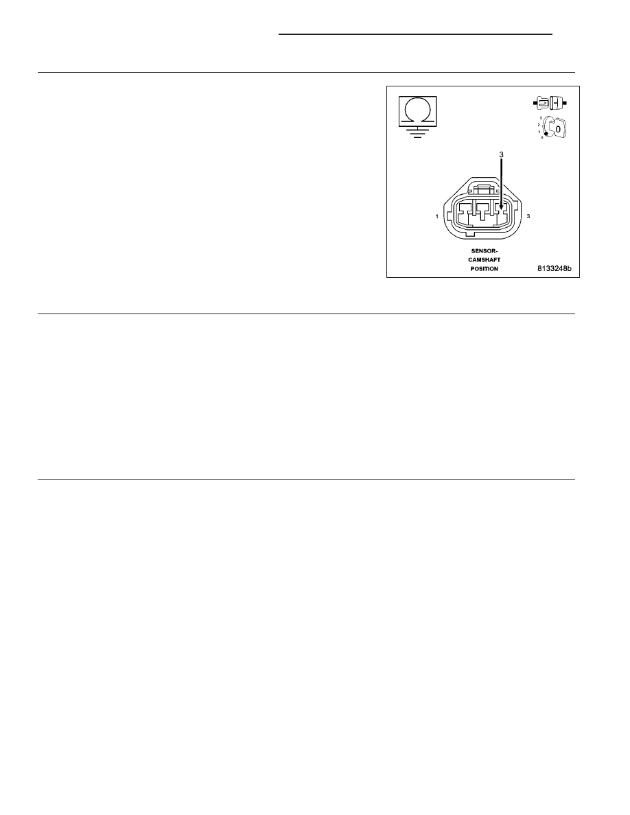
(F856) 5-VOLT SUPPLY CIRCUIT SHORTED TO GROUND
Measure the resistance between ground and the (F856) 5-volt Supply
circuit in the CMP Sensor harness connector.
Is the resistance below 100 ohms?
Yes
>> Repair the short to ground in the (F856) 5-volt Supply cir-
cuit.
Perform the POWERTRAIN VERIFICATION TEST. (Refer to
9 - ENGINE - STANDARD PROCEDURE)
No
>> Go To 13
13.
PCM
NOTE: Before continuing, check the PCM harness connector terminals for corrosion, damage, or terminal
push out. Repair as necessary.
Using the schematics as a guide, inspect the wire harness and connectors. Pay particular attention to all Power and
Ground circuits.
Were there any problems found?
Yes
>> Repair as necessary.
Perform the POWERTRAIN VERIFICATION TEST. (Refer to 9 - ENGINE - STANDARD PROCEDURE)
No
>> Replace and program the Powertrain Control Module per Service Information.
Perform the POWERTRAIN VERIFICATION TEST. (Refer to 9 - ENGINE - STANDARD PROCEDURE)
14.
ERRATIC CMP SIGNAL
With a lab scope probe and the Miller special tool #6801, back probe the (K44) CMP Signal circuit in the CMP
harness connector.
WARNING: When the engine is operating, do not stand in direct line with the fan. Do not put your hands
near the pulleys, belts, or fan. Do not wear loose clothing. Failure to follow these instructions can result in
personal injury or death.
Ignition on, engine not running.
Wiggle the related wire harness and lightly tap the Camshaft Position Sensor.
Observe the lab scope screen.
Allow the engine to idle.
Observe the lab scope screen.
Did the CMP Sensor generate any erratic pulses?
Yes
>> Replace the Camshaft Position Sensor.
Perform the POWERTRAIN VERIFICATION TEST. (Refer to 9 - ENGINE - STANDARD PROCEDURE)
No
>> Go To 15
9 - 318
ENGINE ELECTRICAL DIAGNOSTICS
KJ