Jeep Liberty KJ. Manual - part 479


  Index      Jeep     Jeep Liberty KJ - service repair manual 2006 year


Search            


Content   ..  477  478  479  480   ..


Jeep Liberty KJ. Manual - part 479


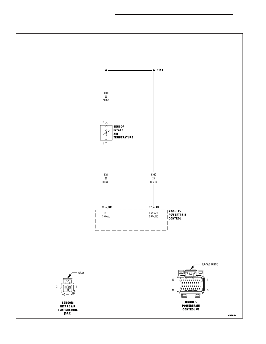
P0112-INTAKE AIR TEMPERATURE SENSOR CIRCUIT LOW

For a complete wiring diagram Refer to Section 8W.

9 - 74

ENGINE ELECTRICAL DIAGNOSTICS

KJ

When Monitored:
With the ignition on and battery voltage greater than 10.4 volts.

Set Condition:
When the Inlet Air Temp Sensor Signal circuit voltage is less than .078 volt for more than 2.8 seconds. One
trip failure. Three good trips to clear the MIL.

Possible Causes

(K21) IAT SIGNAL CIRCUIT SHORTED TO GROUND

(K21) IAT SIGNAL CIRCUIT SHORTED TO THE (K900) SENSOR GROUND CIRCUIT

INTAKE AIR TEMPERATURE SENSOR

PCM

Always perform the Pre-Diagnostic Troubleshooting procedure before proceeding. (Refer to 9 - ENGINE -
DIAGNOSIS AND TESTING).

Diagnostic Test

1.

IAT SENSOR VOLTAGE BELOW 0.078 OF A VOLT

Ignition on, engine not running.

With a scan tool, read the IAT voltage.

Is the voltage below 0.078 of a volt?

Yes

>> Go To 2

No

>> Refer to the INTERMITTENT CONDITION Diagnostic Procedure.

Perform the POWERTRAIN VERIFICATION TEST. (Refer to 9 - ENGINE - STANDARD PROCEDURE)

2.

IAT SENSOR

Turn the ignition off.

Disconnect the IAT Sensor harness connector.

Ignition on, engine not running.

With a scan tool, read IAT voltage.

Is the voltage above 0.05 of a volt?

Yes

>> Replace the Intake Air Temperature Sensor.

Perform the POWERTRAIN VERIFICATION TEST. (Refer to 9 - ENGINE - STANDARD PROCEDURE)

No

>> Go To 3

KJ

ENGINE ELECTRICAL DIAGNOSTICS

9 - 75

3.

(K21) IAT SIGNAL CIRCUIT SHORTED TO GROUND

Turn the ignition off.

Disconnect the C2 PCM harness connector.

Measure the resistance between ground and the (K21) IAT Signal circuit
in the IAT Sensor harness connector.

Is the resistance below 100 ohms?

Yes

>> Repair the short to ground in the (K21) IAT Signal circuit.

Perform the POWERTRAIN VERIFICATION TEST. (Refer to
9 - ENGINE - STANDARD PROCEDURE)

No

>> Go To 4

4.

(K21) IAT SIGNAL CIRCUIT SHORTED TO THE (K900) SENSOR GROUND CIRCUIT

Measure the resistance between the (K21) IAT Signal circuit and the
(K900) Sensor ground circuit in the IAT Sensor harness connector.

Is the resistance below 100 ohms?

Yes

>> Repair the short between the (K900) Sensor ground circuit

and the (K21) IAT Signal circuit.

Perform the POWERTRAIN VERIFICATION TEST. (Refer to
9 - ENGINE - STANDARD PROCEDURE)

No

>> Go To 5

5.

PCM

NOTE: Before continuing, check the PCM harness connector terminals for corrosion, damage, or terminal
push out. Repair as necessary.
Using the schematics as a guide, inspect the wire harness and connectors. Pay particular attention to all Power and
Ground circuits.

Were there any problems found?

Yes

>> Repair as necessary.

Perform the POWERTRAIN VERIFICATION TEST. (Refer to 9 - ENGINE - STANDARD PROCEDURE)

No

>> Replace and program the Powertrain Control Module per Service Information.

Perform the POWERTRAIN VERIFICATION TEST. (Refer to 9 - ENGINE - STANDARD PROCEDURE)

9 - 76

ENGINE ELECTRICAL DIAGNOSTICS

KJ

P0113-INTAKE AIR TEMPERATURE SENSOR CIRCUIT HIGH

For a complete wiring diagram Refer to Section 8W.

KJ

ENGINE ELECTRICAL DIAGNOSTICS

9 - 77


Content   ..  477  478  479  480   ..