Jeep Liberty KJ. Manual - part 478
Theory of Operation
Intake Air Temperature Sensor performance looks at the outputs of three temperature sensors and compare them
under cold start conditions. Following a start to run delay time, the outputs of the ambient, engine coolant, and
intake air temperature sensors will be compared. If the engine coolant and ambient air temperature sensors agree
and the intake air temperature does not agree, the intake air temperature sensor is declared as irrational.
•
When Monitored:
The engine off time is greater than 480 minutes. Ambient Temperature if greater than 4 deg C (38 deg F).
•
Set Condition:
After a calibrated amount of cool down time the PCM compares the ECT Sensor, IAT Sensor, and the Ambient
Air Temp Sensor values. If the IAT Sensor value is not within -10 deg C (18 deg F) of the other two temper-
ature sensors. Two Trip Fault. Three good trips to turn off the MIL.
Possible Causes
(K21) IAT SIGNAL CIRCUIT SHORTED TO BATTERY VOLTAGE
(K21) IAT SIGNAL CIRCUIT OPEN
(K900) SENSOR GROUND CIRCUIT OPEN
(K21) IAT SIGNAL CIRCUIT SHORTED TO GROUND
(K21) IAT SIGNAL CIRCUIT SHORTED TO THE (K900) SENSOR GROUND CIRCUIT
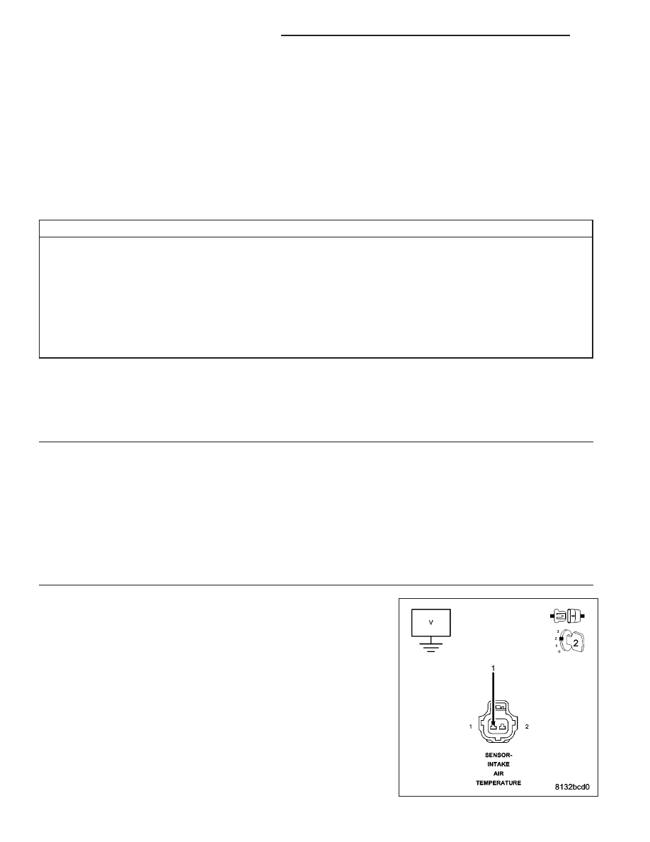
INTAKE AIR TEMPERATURE SENSOR
PCM
Always perform the Pre-Diagnostic Troubleshooting procedure before proceeding. (Refer to 9 - ENGINE -
DIAGNOSIS AND TESTING).
Diagnostic Test
1.
ACTIVE DTC
Ignition on, engine not running.
With a scan tool, read DTCs.
Is the DTC active at this time?
Yes
>> Go To 2
No
>> Refer to the INTERMITTENT CONDITION Diagnostic Procedure.
Perform the POWERTRAIN VERIFICATION TEST. (Refer to 9 - ENGINE - STANDARD PROCEDURE)
2.
(K21) IAT SIGNAL CIRCUIT SHORTED TO BATTERY VOLTAGE
Turn the ignition off.
Disconnect the C2 PCM harness connector.
Disconnect the IAT Sensor harness connector.
NOTE: Visually inspect both the component and the PCM connec-
tors. Look for damaged, partially broken wires, and backed out or
corroded terminals.
Ignition on, engine not running.
9 - 70
ENGINE ELECTRICAL DIAGNOSTICS
KJ