Jeep Liberty KJ. Manual - part 166
POWER FOLDAWAY MIRROR SWITCH - EXPORT
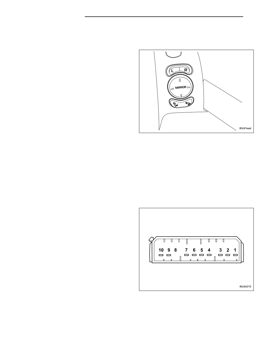
DESCRIPTION
These vehicles may be equipped with Power Fold-
away Mirrors. This feature allows both the driver and
passenger side view mirrors to fold inward (retract) on
demand. The vehicle has an additional switch located
below the power mirror switch that controls the folding
function of the mirror assembly.
The fold-away side view mirror is attached to the vehi-
cle’s door in the same manner as mirrors without the
fold-away option. The fold-away mirrors unique option
is the internal motor which allows the mirrors to fold
inward. The fold-away mirror motor is not serviceable
separately and if a motor is found to be faulty, the
entire side view mirror must be replaced.
OPERATION
When the mirror retract switch is depressed, both of the side view mirrors will fold inward, Thus making the overall
width of the vehicle the smallest possible. This can be helpful were parking space is a absolute minimum.
The power fold away mirrors will operate only when the ignition is in the On position.
The power fold away mirror system consists of the following components: mirror switch, side view mirror, relay,
wires and fuse. Refer to the appropriate wiring information. The wiring information includes wiring diagrams, proper
wire and connector repair procedures, details of wire harness routing and retention, connector pin-out information
and location views for the various wire harness connectors, splices and grounds.
DIAGNOSIS AND TESTING - POWER FOLDAWAY MIRROR SWITCH - EXPORT
1. Disconnect and isolate the battery negative cable.
2. Remove power foldaway mirror switch (Refer to 8 -
ELECTRICAL/POWER
MIRRORS/POWER
MIR-
ROR SWITCH - REMOVAL).
3. Disconnect wire harness connector.
4. Using a ohmmeter, test for continuity between the
terminals of the switch.
5. If results shown in the table are not obtained,
replace the switch.
8N - 86
POWER MIRRORS
KJ