Jeep Liberty KJ. Manual - part 158


  Index      Jeep     Jeep Liberty KJ - service repair manual 2006 year


Search            


Content   ..  156  157  158  159   ..


Jeep Liberty KJ. Manual - part 158


Possible Causes

(P33) DOOR LOCK RELAY OUTPUT WIRE OPEN

(P35) DOOR UNLOCK RELAY OUTPUT WIRE OPEN

DOOR LOCK MOTOR - OPEN

Diagnostic Test

1.

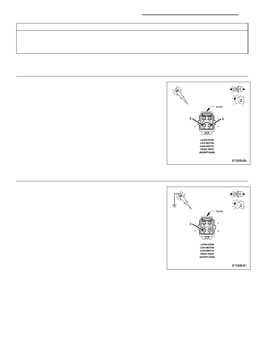
CHECK DOOR LOCK MOTOR

Remove the inner door trim panel to gain access to the Door Lock
Motor connector.

Disconnect the appropriate Door Lock Motor connector.

Turn ignition on.

Connect a test light between the (P33) Lock Relay Output and the
(P35) Unlock Relay Output circuits in the door lock motor connector.

Press the door lock switch to the Lock and Unlock positions.

Did the test light illuminate when the lock switch was pressed
in both directions?

Yes

>> Replace the Door Lock Motor.

Perform BODY VERIFICATION TEST - VER 1. (Refer to 8 -
ELECTRICAL/ELECTRONIC

CONTROL

MODULES

-

STANDARD PROCEDURE)

No

>> Go To 2

2.

CHECK (P35) DOOR UNLOCK RELAY OUTPUT WIRE FOR AN OPEN

Using a 12-volt test light connected to ground, check the (P35) Door
Unlock Relay Output circuit.

With the scan tool, actuate the Door Unlock Relay.

Does the test light illuminate brightly when the relay is actu-
ated?

Yes

>> Go To 3

No

>> Repair the (P35) Door Unlock Relay Output wire for an

open.

Perform BODY VERIFICATION TEST - VER 1. (Refer to 8 -
ELECTRICAL/ELECTRONIC

CONTROL

MODULES

-

STANDARD PROCEDURE)

8N - 54

POWER LOCKS - ELECTRICAL DIAGNOSTICS

KJ

3.

CHECK(P33) DOOR LOCK RELAY OUTPUT WIRE FOR AN OPEN

Turn ignition off.

Using a 12-volt test light connected to ground, check the (P33) Door
Lock Relay Output circuit.

With the scan tool, actuate the Door Lock Relay.

Does the test light illuminate brightly when the relay is actu-
ated?

Yes

>> Test Complete.

No

>> Repair the (P33) Door Lock Relay Output wire for an open.

Perform BODY VERIFICATION TEST - VER 1. (Refer to 8 -
ELECTRICAL/ELECTRONIC

CONTROL

MODULES

-

STANDARD PROCEDURE)

KJ

POWER LOCKS - ELECTRICAL DIAGNOSTICS

8N - 55

*REMOTE KEYLESS ENTRY INOPERATIVE

For a complete wiring diagram Refer to Section 8W.

Possible Causes

DOOR LOCK SYSTEM PROBLEM

RKE TRANSMITTER BATTERY VOLTAGE LOW

RKE TRANSMITTER NOT PROGRAMMED

RKE TRANSMITTER DEFECTIVE

BODY CONTROL MODULE

SKREEM MODULE - RKE INOPERATIVE

1.

DOOR LOCKS SYSTEM CHECK

Operate the door locks from both of the door lock switches.

Did the door locks respond properly to both of the door lock switches?

Yes

>> Go To 2

No

>> Refer to Power Door Locks/RKE in the Symptom List for the appropriate symptom.

2.

9001 TESTER AVAILABLE

NOTE: NOTE: Ensure there is communication between the SKREEM and the BODY CONTROL MODULE
before proceeding.

Do you have access to the Miller Special Tool

(

9001 RF DETECTOR

(

?

No

>> Go To 3

Yes

>> Go To 8

3.

TEST BATTERIES WITH VOLTMETER

Using a voltmeter, test the Batteries in the RKE Transmitter.

Is the voltage above 3.0 volts in each battery?

Yes

>> Go To 4

No

>> Replace the Batteries.

Perform BODY VERIFICATION TEST - VER 1. (Refer to 8 - ELECTRICAL/ELECTRONIC CONTROL
MODULES - STANDARD PROCEDURE)

4.

CHECK BODY CONTROL MODULE

With the scan tool actuate the door LOCK and then door UNLOCK relays.

Do the door locks operate using the scan tool?

Yes

>> Go To 5

No

>> Replace the Body Control Module in accordance with Service Information..

Perform BODY VERIFICATION TEST - VER 1. (Refer to 8 - ELECTRICAL/ELECTRONIC CONTROL
MODULES - STANDARD PROCEDURE)

8N - 56

POWER LOCKS - ELECTRICAL DIAGNOSTICS

KJ

5.

RKE TRANSMITTER NOT RESPONDING

With the scan tool select THEFT ALARM, SKIM, MONITORS and observe the “FOB No.” and

9

FOB Button

9

.

Press the LOCK button and then the UNLOCK button on the Transmitter.

Does the scan tool display:

(

UNLOCK

(

,

(

LOCK

(

and the

(

FOB Number

(

?

Yes

>> Replace the Body Control Module in accordance with Service Information.

Perform BODY VERIFICATION TEST - VER 1. (Refer to 8 - ELECTRICAL/ELECTRONIC CONTROL
MODULES - STANDARD PROCEDURE)

No

>> Go To 6

6.

PROGRAM RKE TRANSMITTER WITH THE SCAN TOOL

With the scan tool select THEFT ALARM, SKIM, then PROGRAM NEW KEY. Follow instructions on the screen.

Exit PROGRAM NEW KEY. Try the Door Locks using the Transmitter.

Did the Door Locks respond properly to the Transmitter commands ?

Yes

>> Repair complete. Using the scan tool, program other Transmitters used with this Vehicle.

Perform BODY VERIFICATION TEST - VER 1. (Refer to 8 - ELECTRICAL/ELECTRONIC CONTROL
MODULES - STANDARD PROCEDURE)

No

>> Go To 7

7.

USE KNOWN GOOD TRANSMITTER

Secure a known good Transmitter.

Using the scan tool select THEFT ALARM, SKIM then PROGRAM NEW KEY and follow the instructions on the scan
tool screen.

Exit PROGRAM new key. Try the Door Locks using the Transmitter.

NOTE: When repairs are complete ensure all transmitters used with this vehicle are programmed.

Did the Door Locks respond properly to the Transmitter commands ?

Yes

>> Replace the Transmitter. Program all Transmitters that will be used with this Vehicle.

Perform BODY VERIFICATION TEST - VER 1. (Refer to 8 - ELECTRICAL/ELECTRONIC CONTROL
MODULES - STANDARD PROCEDURE)

No

>> Replace the Sentry Key RemotE Entry Module in accordance with service information.

Perform BODY VERIFICATION TEST - VER 1. (Refer to 8 - ELECTRICAL/ELECTRONIC CONTROL
MODULES - STANDARD PROCEDURE)

8.

TEST TRANSMITTER WITH TESTER

Using the 9001 RF Detector, follow the instructions on the back of the tester and test the transmitter several times.

Does the signal strength measure

(

STRONG

(

?

Yes

>> Go To 9

No

>> Check and replace the batteries if they are under 3.0 volts each and retest the transmitter. If the bat-

teries are okay, replace the transmitter.

Perform BODY VERIFICATION TEST - VER 1. (Refer to 8 - ELECTRICAL/ELECTRONIC CONTROL
MODULES - STANDARD PROCEDURE)

KJ

POWER LOCKS - ELECTRICAL DIAGNOSTICS

8N - 57


Content   ..  156  157  158  159   ..