Content .. 1472 1473 1474 1475 ..
Jeep Liberty KJ. Manual - part 1474
6.
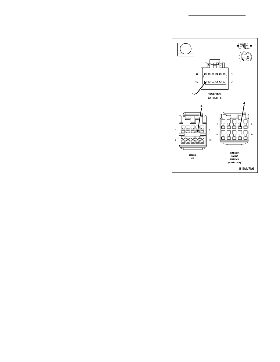
(D25) PCI BUS CIRCUIT OPEN
Turn the ignition off.
Disconnect the Radio C2 harness connector.
NOTE: If equipped disconnect the HFM C2 harness connector.
Measure the resistance of the (D25) PCI Bus circuit between either the
Radio C2 harness connector (or if equipped the HFM C2 harness con-
nector) and the Satellite Receiver harness connector.
Is the resistance below 5.0 ohms?
Yes
>> Replace the Satellite Receiver in accordance with the ser-
vice information.
Perform BODY VERIFICATION TEST – VER 1. (Refer to 8
-
ELECTRICAL/ELECTRONIC
CONTROL MODULES
-
STANDARD PROCEDURE).
No
>> Repair the (D25) PCI Bus circuit for an open.
Perform BODY VERIFICATION TEST – VER 1. (Refer to 8
-
ELECTRICAL/ELECTRONIC
CONTROL MODULES
-
STANDARD PROCEDURE).
8E - 108
ELECTRONIC CONTROL MODULES - ELECTRICAL DIAGNOSTIC
KJ