Content .. 1469 1470 1471 1472 ..
Jeep Liberty KJ. Manual - part 1471
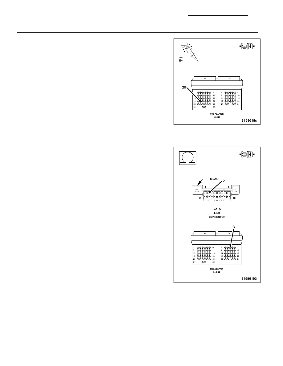
3.
(Z104) GROUND CIRCUIT OPEN
Turn the ignition off.
Using a 12-volt test light connected to 12-volts, probe the (Z104) ground
circuit.
Did the test light illuminate brightly?
Yes
>> Go To 4
No
>> Repair the (Z104) Ground circuit for an open.
Perform the AIRBAG VERIFICATION TEST – VER 1.
4.
(D25) PCI BUS CIRCUIT OPEN
Disconnect the scan tool from the DLC connector.
Measure the resistance of the (D25) PCI Bus circuit between the DLC
and the Occupant Restraint Controller C1 harness connector.
Is the resistance below 5.0 ohms?
Yes
>> Replace the Occupant Restraint Controller Module in accor-
dance with the service information.
Perform the AIRBAG VERIFICATION TEST – VER 1.
No
>> Repair the (D25) PCI Bus circuit for an open.
Perform the AIRBAG VERIFICATION TEST – VER 1.
8E - 96
ELECTRONIC CONTROL MODULES - ELECTRICAL DIAGNOSTIC
KJ