Content .. 1465 1466 1467 1468 ..
Jeep Liberty KJ. Manual - part 1467
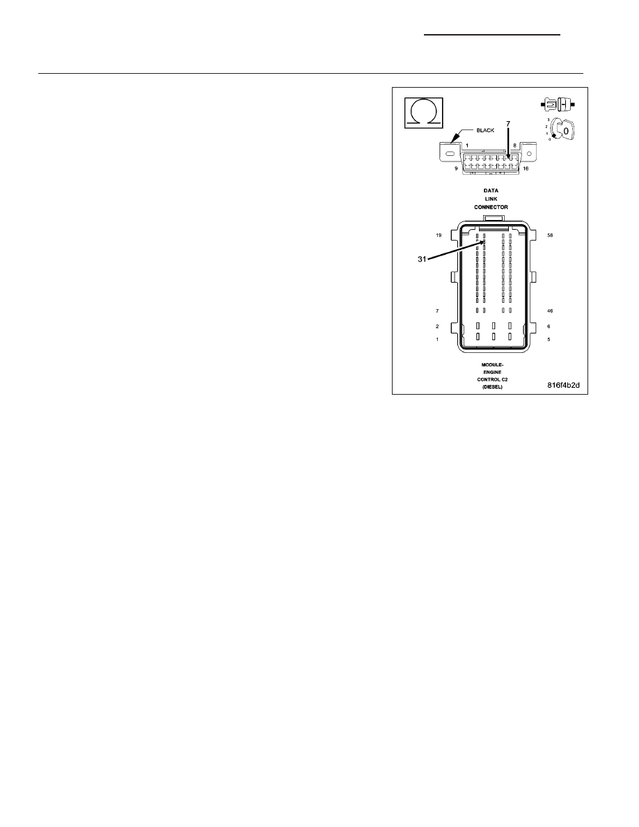
7.
(D21) SCI CIRCUIT OPEN AT THE DLC
Turn the ignition off.
Measure the resistance of the (D21) SCI Transmit circuit between the
ECM connector and the DLC connector.
Is resistance below 5.0 ohms?
Yes
>> Replace the Engine Control Module in accordance with the
service information.
Perform the ECM VERIFICATION TEST.
No
>> Repair the (D21) SCI Transmit circuit for an open.
Perform the BODY VERIFICATION TEST–VER 1. (Refer to
8 - ELECTRICAL/ELECTRONIC CONTROL MODULES -
STANDARD PROCEDURE)
8E - 80
ELECTRONIC CONTROL MODULES - ELECTRICAL DIAGNOSTIC
KJ