Jeep Liberty KJ. Manual - part 1439


  Index      Jeep     Jeep Liberty KJ - service repair manual 2006 year


Search            


Content   ..  1437  1438  1439  1440   ..


Jeep Liberty KJ. Manual - part 1439


INTERNATIONAL

COUNTRY CODE

RADIO BROADCAST STD.

ZIMBABWE (8G1)

ROW

OPERATION

The radio receiver operates on ignition switched battery current that is available only when the ignition switch is in
the On or Accessory positions. The electronic digital clock function of the radio operates on fused battery current
supplied through the IOD fuse, regardless of the ignition switch position.

For complete circuit diagrams, refer to the appropriate wiring information.

REMOVAL

1. Disconnect and isolate the battery negative cable.

2. Remove the instrument panel center trim panel.

3. Remove the radio mounting fasteners.

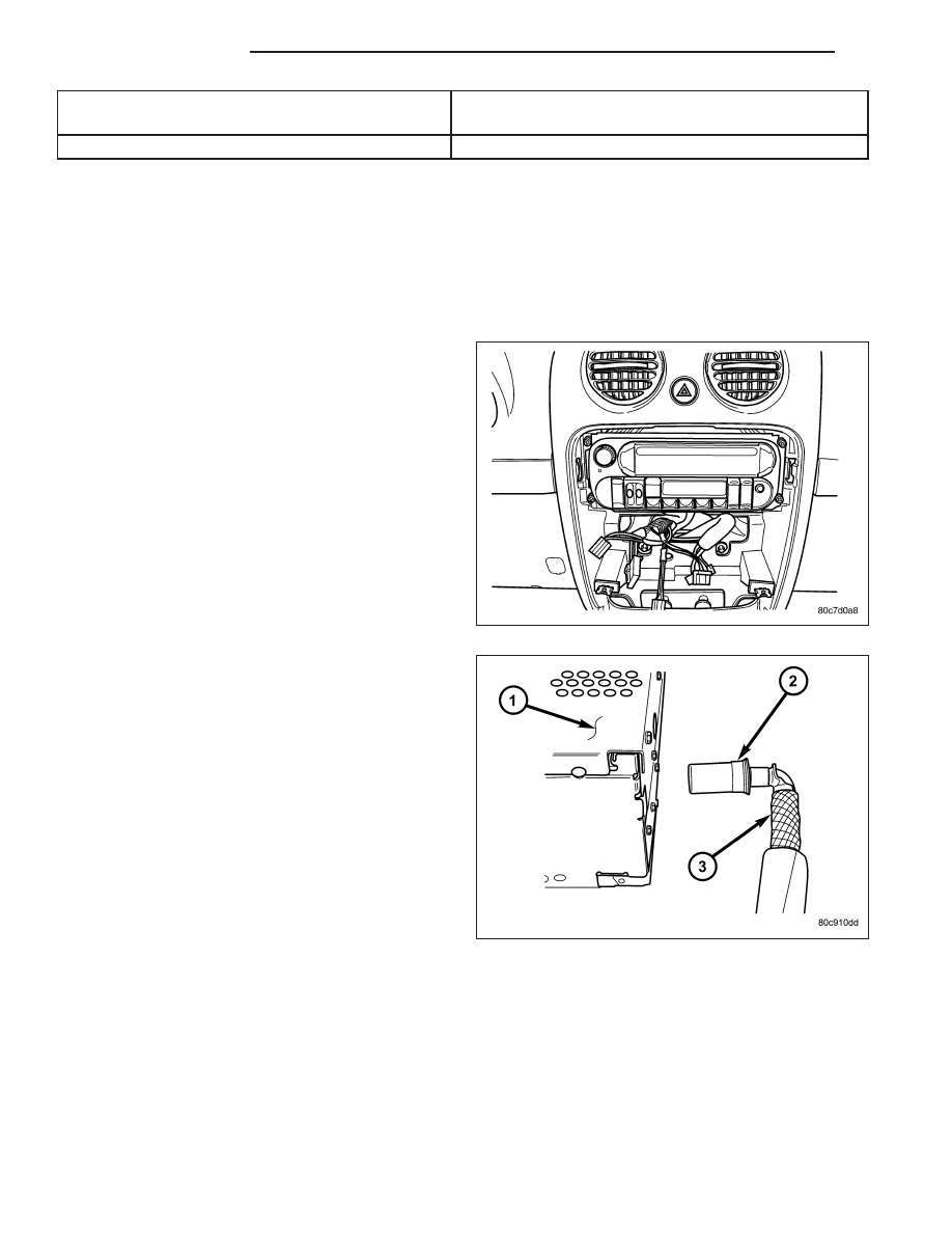
CAUTION: Pulling the antenna cable straight out
of the radio without pulling on the locking antenna
connector could damage the cable or radio.

4. Disconnect the antenna cable by pulling the locking

antenna connector (2) away from the radio.

5. Disconnect the electrical harness connector(s).

6. Remove radio from instrument panel.

8A - 60

AUDIO/VIDEO

KJ

INSTALLATION

1. Connect the wire harness connector(s).

2. Connect the antenna cable.

3. Install the radio to the instrument panel.

4. Install and tighten the radio mounting fasteners.

5. Install the instrument panel center trim panel.

6. Connect the battery negative cable.

KJ

AUDIO/VIDEO

8A - 61

RADIO NOISE SUPPRESSION COMPONENTS

DESCRIPTION

Radio Frequency Interference (RFI) and ElectroMagnetic Interference (EMI) can be produced by any on-board or
external source of electromagnetic energy. These electromagnetic energy sources can radiate electromagnetic sig-
nals through the air, or conduct them through the vehicle electrical system.

When the audio system converts RFI or EMI to an audible acoustic wave form, it is referred to as radio noise. This
undesirable radio noise is generally manifested in the form of “buzzing,” “hissing,” “popping,” “clicking,” “crackling,”
and/or “whirring” sounds. In most cases, RFI and EMI radio noise can be suppressed using a combination of vehicle
and component grounding, filtering and shielding techniques. This vehicle is equipped with factory-installed radio
noise suppression devices that were designed to minimize exposure to typical sources of RFI and EMI; thereby,
minimizing radio noise complaints.

Radio noise suppression is accomplished primarily through circuitry or devices that are integral to the factory-in-
stalled radios, audio power amplifiers and other on-board electrical components such as generators, wiper motors,
blower motors, and fuel pumps that have been found to be potential sources of RFI or EMI. External radio noise
suppression devices that are used on this vehicle to control RFI or EMI, and can be serviced, include the following:

Engine-to-body ground strap - This length of braided ground strap has an eyelet terminal connector crimped
to each end. One end is secured to the engine cylinder head(s). The other is secured to the plenum.

Resistor-type spark plugs - This type of spark plug has an internal resistor connected in series between the
spark plug terminal and the center electrode to help reduce the production of electromagnetic radiation that
can result in radio noise.

OPERATION

There are two common strategies that can be used to suppress Radio Frequency Interference (RFI) and Electro-
Magnetic Interference (EMI) radio noise. The first suppression strategy involves preventing the production of RFI
and EMI electromagnetic signals at their sources. The second suppression strategy involves preventing the recep-
tion of RFI and EMI electromagnetic signals by the audio system components.

The use of braided ground straps in key locations is part of the RFI and EMI prevention strategy. These ground
straps ensure adequate ground paths, particularly for high current components such as many of those found in the
starting, charging, ignition, engine control and transmission control systems. An insufficient ground path for any of
these high current components may result in radio noise caused by induced voltages created as the high current
seeks alternative ground paths through components or circuits intended for use by, or in close proximity to the audio
system components or circuits.

Preventing the reception of RFI and EMI is accomplished by ensuring that the audio system components are cor-
rectly installed in the vehicle. Loose, corroded or improperly soldered wire harness connections, improperly routed
wiring and inadequate audio system component grounding can all contribute to the reception of RFI and EMI. A
properly grounded antenna body and radio chassis, as well as a shielded antenna coaxial cable with clean and tight
connections will each help reduce the potential for reception of RFI and EMI.

8A - 62

AUDIO/VIDEO

KJ

REMOVAL

2.4L ENGINE

1. Disconnect and isolate the battery negative cable.

2. Remove the retaining bolt (2) from the engine cyl-

inder head.

3. Remove the retaining nut (2) from the plenum.

2.5L ENGINE

1. Disconnect and isolate the battery negative cable.

2. Remove the retaining bolt (2) from the engine cyl-

inder head.

KJ

AUDIO/VIDEO

8A - 63


Content   ..  1437  1438  1439  1440   ..