Content .. 1395 1396 1397 1398 ..
Jeep Liberty KJ. Manual - part 1397
WATER PUMP
DESCRIPTION
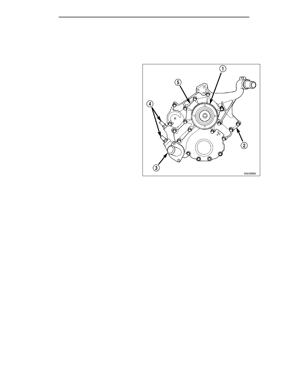
3.7L ENGINE
A centrifugal water pump (5) circulates coolant through
the water jackets, passages, intake manifold, radiator
core, cooling system hoses and heater core. The
pump is driven from the engine crankshaft by a single
serpentine drive belt.
The water pump impeller is pressed onto the rear of a
shaft that rotates in bearings pressed into the housing.
The housing has two small holes to allow seepage to
escape. The water pump seals are lubricated by the
antifreeze in the coolant mixture. No additional lubrica-
tion is necessary.
Both heater hoses are connected to fittings on the tim-
ing chain front cover. The water pump is also mounted
directly to the timing chain cover and is equipped with
a non serviceable integral pulley.
2.8L DIESEL ENGINE
The water pump on the 2.8L CRD diesel has a die cast aluminum housing. It bolts to a aluminum housing which
attaches to the engine block.
DESCRIPTION - WATER PUMP BYPASS - 3.7L
The 3.7L engine uses an internal water/coolant bypass system. The design uses galleries in the timing chain cover
to circulate coolant during engine warm-up preventing the coolant from flowing through the radiator. The thermostat
uses a stub shaft located at the rear of the thermostat to control flow through the bypass gallery.
OPERATION
2.8L DIESEL ENGINE
The water pump is used to circulate coolant through the cooling system. The coolant is pumped through the engine
block, cylinder head, heater core, EGR cooler, viscous heater, and radiator.
3.7L ENGINES
A centrifugal water pump circulates coolant through the water jackets, passages, intake manifold, radiator core, cool-
ing system hoses and heater core, this coolant absorbs the heat generated when the engine is running. The pump
is driven by the engine crankshaft via a drive belt.
7 - 66
ENGINE
KJ