Jeep Liberty KJ. Manual - part 110


  Index      Jeep     Jeep Liberty KJ - service repair manual 2006 year


Search            


Content   ..  108  109  110  111   ..


Jeep Liberty KJ. Manual - part 110


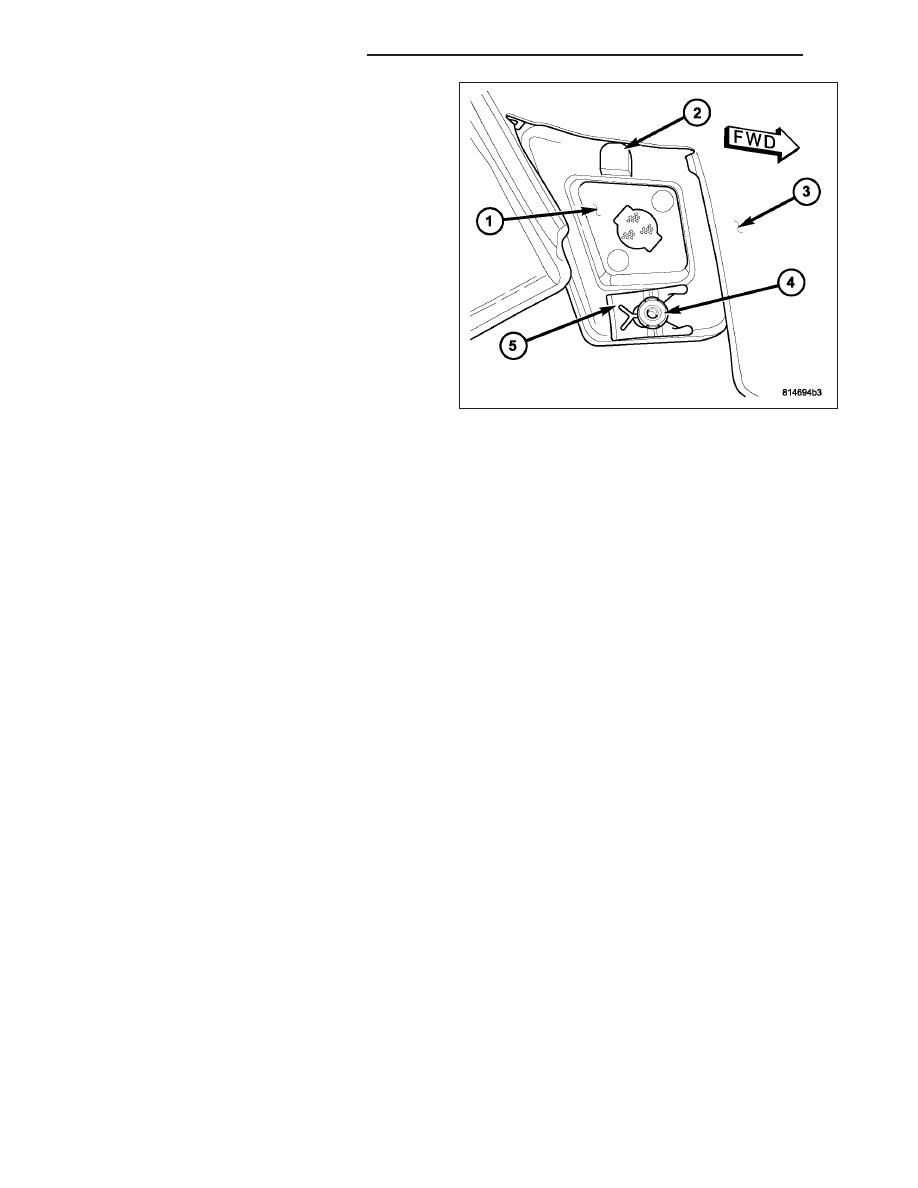
1. Position the front side marker lamp unit (1) to the

lamp mounting hole on the outside of the fascia.

2. Engage the tab (2) at the top of the lamp into the

notch at the top of the mounting hole then push the
pin (4) on the lower end of the lamp through the
round hole at the base of the mounting hole.

3. Reach between the front of the adjacent right or

left front fender wheel liner and the lower bumper
fascia (3) to access the back of the lamp housing.

4. Slide the retaining clip (5) onto the pin on the lower

end of the lamp housing to secure the lamp to the
fascia.

5. If the vehicle is so equipped, align the socket and

bulb with the keyed opening on the back of the
housing.

6. If the vehicle is so equipped, insert the socket and

bulb into the housing until the socket is firmly
seated.

7. If the vehicle is so equipped, rotate the socket clockwise about 30 degrees to lock it into place.

8. Reinstall the four fasteners securing the front of the wheel liner to the lower edge of the fascia and the outboard

surface of the frame rail ahead of the front wheel.

9. Reconnect the battery negative cable.

8L - 98

LAMPS/LIGHTING - EXTERIOR

KJ

MULTI-FUNCTION SWITCH

DESCRIPTION

The multi-function switch (1) is located on the steering column, just below the steering wheel. The only visible com-
ponents of the multi-function switch are the right (2) and left control stalks (3). One stalk extends through the steer-
ing column shrouds on each side of the steering column. The remainder of the switch including its mounting
provisions, its electrical connection, and the turn signal cancel actuator (4) are concealed beneath the shrouds.

The switch housing and controls are constructed of molded black plastic. A saddle-like formation in the center of the
lower switch housing straddles the steering column tube just below the column lock housing, and two locating posts
integral to the lower surface of the switch housing engage two holes in the forward-facing side of the lock housing.
Also several integral ledge-like locating tabs on the switch housing are supported and located by several mating
points on the column lock housing. When the steering column shrouds are installed on the column, mounting tabs
on the switch housing and the clockspring are clamped to the lock housing by the same two screws that secure the
column shrouds to the column and each other.

There are several versions of the multi-function switch to support both optional equipment and regulatory equipment
that is required only in certain markets. Each multi-function switch control stalk has both white nomenclature and
International Control and Display Symbol graphics applied to it, which clearly identify its many functions. Each con-
trol stalk has a control knob (5 and 8) on its end with a flattened face to allow it to be easily rotated. On vehicles
equipped with optional front fog lamps, the knob on the end of left control stalk can also be pulled outward to select
those lamps.

Each control stalk also features a knurled control ring (6 and 7) located just below the control knob. The left control
stalk is dedicated to providing driver controls for the interior and exterior lighting systems, while the right control
stalk is dedicated to providing driver controls for the front and rear wiper systems.

Two integral connector receptacles on the multi-function switch housing connect the switch to the vehicle electrical
system through two dedicated take outs and connectors of the instrument panel wire harness. The left connector
receptacle contains nine terminal pins for the lighting control circuits of the switch, while the right connector recep-
tacle contains six terminal pins for the wiper control circuits of the switch.

The multi-function switch cannot be adjusted or repaired. If any function of the switch is ineffective, or if the switch
is damaged, the entire switch must be replaced as a unit.

LEFT CONTROL STALK

The left (lighting) control stalk of the multi-function switch supports the following functions and features:

Front Fog Lamps - For vehicles so equipped, the left multi-function switch control knob provides detent
switching for the optional front fog lamps.

Headlamps - The left multi-function switch control knob provides detent switching for the headlamps.

Headlamp Beam Selection - The left multi-function switch control stalk provides detent switching for selection
of the headlamp high or low beams.

KJ

LAMPS/LIGHTING - EXTERIOR

8L - 99

Headlamp Optical Horn - The left multi-function switch control stalk includes momentary switching of the
headlamp high beam circuits to provide an optical horn feature (sometimes referred to as flash-to-pass), which
allows the vehicle operator to momentarily flash the headlamp high beams as an optical signalling device.

Interior Lamps Defeat - The left multi-function switch control ring provides detent switching to defeat the illu-
mination of all interior courtesy lamps when a door, the rear flip-up glass, or the tailgate are opened.

Interior Lamps On - The left multi-function switch control ring provides detent switching to simultaneously
illuminate all interior courtesy lamps.

Panel Lamps Dimming - The left multi-function switch control ring provides simultaneous adjustable control of
the illumination intensity of all instrument panel lighting at one of six available illumination intensity levels.

Parade Mode - The left multi-function switch control ring provides detent switching for a parade mode that
maximizes the illumination intensity of all instrument panel lighting for visibility when driving in daylight with the
exterior lamps turned on.

Park Lamps - The left multi-function switch control knob provides detent switching for the park lamps.

Rear Fog Lamps - For vehicles so equipped, the left multi-function switch control knob provides detent switch-
ing for the optional rear fog lamps. Rear fog lamps are optional only for vehicles manufactured for certain
markets, where they are required.

Turn Signal Control - The left multi-function switch control stalk provides both momentary non-detent switch-
ing and detent switching with automatic cancellation for both the left and right turn signal lamps.

RIGHT CONTROL STALK

The right (wiper) control stalk of the multi-function switch supports the following functions and features:

Continuous Front Wipe Modes - The right multi-function switch control knob provides two continuous front
wipe switch positions, low speed or high speed.

Continuous Rear Wipe Mode - The right multi-function switch control ring provides one continuous rear wipe
switch position.

Front Washer Mode - The right multi-function switch control stalk provides front washer system operation.

Front Wipe-After-Wash Mode - The right multi-function switch control stalk provides a wipe-after-wash mode.

Front Wiper Mist Mode - The right multi-function switch control stalk provides a front wiper system mist mode.

Intermittent Front Wipe Mode - The right multi-function switch control knob provides an intermittent front wipe
mode with five delay interval positions.

Intermittent Rear Wipe Mode - The right multi-function switch control ring provides one fixed interval inter-
mittent rear wipe mode switch position.

Rear Washer Mode - The right multi-function switch control ring provides rear washer system operation.

OPERATION

The multi-function switch uses a combination of resistor multiplexed and conventionally switched outputs to control
the many functions and features it provides. The switch receives battery voltage on a fused ignition switch output
(run-acc) circuit from a fuse in the Junction Block (JB) whenever the ignition switch is in the On or Accessory posi-
tions. The switch receives a path to ground at all times through a ground stud on the driver side instrument panel
end bracket near the Junction Block (JB).

The multi-function switch can be diagnosed using conventional diagnostic tools and methods. However, proper test-
ing of the multiplexed inputs to the Body Control Module (BCM) requires the use of a diagnostic scan tool. Refer to
the appropriate diagnostic information.

Following are brief descriptions of how each of the two multi-function switch control stalks operate to control the
functions and features they provide.

LEFT CONTROL STALK

The left (lighting) control stalk of the multi-function switch operates as follows:

Front Fog Lamps - For vehicles so equipped, the control knob on the end of the multi-function switch left
(lighting) control stalk is pulled outward to activate the optional front fog lamps. The control knob is mechan-
ically keyed so that it cannot be pulled outward unless it is first rotated to turn On the exterior lighting. The
multi-function switch provides a resistor multiplexed output to the Body Control Module (BCM) on a fog lamp
switch sense circuit, and the BCM responds by energizing or de-energizing the front fog lamp relay in the
Junction Block (JB).

8L - 100

LAMPS/LIGHTING - EXTERIOR

KJ

Headlamps - The control knob on the end of the multi-function switch left (lighting) control stalk is rotated
forward to its second detent position to activate the headlamps. The multi-function switch provides a resistor
multiplexed output to the Body Control Module (BCM) on a headlamp switch sense circuit, and the BCM
responds by energizing or de-energizing the selected low or high beam relay (Daytime Running Lamp relay in
Canadian vehicles) in the Junction Block (JB).

Headlamp Beam Selection - The left (lighting) control stalk of the multi-function switch is pulled towards the
steering wheel past a detent to actuate the integral beam select switch circuitry. Each time the control stalk is
activated in this manner, the opposite headlamp beam from what is currently selected will be energized. The
multi-function switch provides a ground output to the Body Control Module (BCM) on a high beam switch
sense circuit, and the BCM responds by energizing or de-energizing the selected low or high beam relay (Day-
time Running Lamp relay in Canadian vehicles) in the Junction Block (JB).

Headlamp Optical Horn - The left (lighting) control stalk of the multi-function switch is pulled towards the
steering wheel to just before a detent, to momentarily activate the headlamp optical horn feature. The high
beams will remain illuminated until the control stalk is released. The multi-function switch provides a ground
output on a high beam relay control circuit to energize the headlamp high beam relay (Daytime Running Lamp
relay in Canadian vehicles) in the Junction Block (JB).

Interior Lamps Defeat - The control ring on the multi-function switch left (lighting) control stalk is rotated to a
full rearward (clockwise) detent to defeat the illumination of all interior courtesy lamps. The multi-function
switch provides a resistor multiplexed output to the Body Control Module (BCM) on a panel lamps dimmer
switch circuit, and the BCM responds by de-energizing its internal courtesy lamp driver circuit.

Interior Lamps On - The control ring on the multi-function switch left (lighting) control stalk is rotated to a full
forward detent to illuminate all interior courtesy lamps. The multi-function switch provides a resistor multiplexed
output to the Body Control Module (BCM) on a panel lamps dimmer switch circuit, and the BCM responds by
energizing its internal courtesy lamp driver circuit.

Panel Lamps Dimming - The control ring on the multi-function switch left (lighting) control stalk is rotated to
one of six minor intermediate detents to simultaneously select the desired illumination intensity of all adjustable
instrument panel and instrument cluster lighting. The control ring is rotated rearward to dim, or forward to
brighten. The multi-function switch provides a resistor multiplexed output to the Body Control Module (BCM) on
a panel lamps dimmer switch circuit, and the BCM responds by sending an electronic panel lamps dimming
level message to the ElectroMechanical Instrument Cluster (EMIC) over the Programmable Communications
Interface (PCI) data bus. The EMIC electronic circuitry then provides the proper PWM output to the cluster
illumination lamps and the Vacuum Florescent Display (VFD) on the EMIC circuit board, and provides a match-
ing Pulse Width Modulation (PWM) output on the hard wired fused panel lamps dimmer switch signal circuit.

Parade Mode - The control ring on the multi-function switch left (lighting) control stalk is rotated to an inter-
mediate detent that is one detent rearward from the full forward detent to select the Parade mode. The multi-
function switch provides a resistor multiplexed output to the Body Control Module (BCM) on a panel lamps
dimmer switch circuit, and the BCM responds by sending an electronic panel lamps dimming level message to
the ElectroMechanical Instrument Cluster (EMIC) over the Programmable Communications Interface (PCI) data
bus. The EMIC electronic circuitry then provides the proper PWM output to the cluster illumination lamps and
the VFD on the EMIC circuit board, and provides a matching PWM output on the hard wired fused panel lamps
dimmer switch signal circuit to illuminate all lamps at full (daylight) intensity with the exterior lamps turned On.

Park Lamps - The control knob on the end of the multi-function switch left (lighting) control stalk is rotated
forward to its first detent from the Off position to activate the park lamps. The multi-function switch provides a
resistor multiplexed output to the Body Control Module (BCM) on a headlamp switch sense circuit, and the
BCM responds by energizing or de-energizing the park lamp relay in the Junction Block (JB).

Rear Fog Lamps - For vehicles so equipped, the control knob on the end of the multi-function switch left
(lighting) control stalk is rotated forward to its third detent position to activate the rear fog lamps. The multi-
function switch provides a resistor multiplexed output to the Body Control Module (BCM) on a headlamp switch
sense circuit, and the BCM responds by energizing or de-energizing the rear fog lamp relay in the Junction
Block (JB). Rear fog lamps are optional only for vehicles manufactured for markets, where they are required.

Turn Signal Control - The left (lighting) control stalk of the multi-function switch is moved upward to activate
the right turn signal circuitry, and downward to activate the left turn signal circuitry. The turn signal switch has
a detent position in each direction that provides turn signals with automatic cancellation, and an intermediate,
momentary position in each direction that provides turn signals only until the left multi-function switch control
stalk is released. When the control stalk is moved to a turn signal switch detent position, the cancel actuator
extends toward the center of the steering column. A turn signal cancel cam is integral to the clockspring and
rotates with the steering wheel. The cam lobe contacts the cancel actuator when it is extended from the multi-

KJ

LAMPS/LIGHTING - EXTERIOR

8L - 101


Content   ..  108  109  110  111   ..