Jeep Liberty KJ. Manual - part 109


  Index      Jeep     Jeep Liberty KJ - service repair manual 2006 year


Search            


Content   ..  107  108  109  110   ..


Jeep Liberty KJ. Manual - part 109


REMOVAL

WARNING: To avoid personal injury or death, on vehicles equipped with airbags, disable the supplemental
restraint system before attempting any steering wheel, steering column, airbag, occupant classification sys-
tem, seat belt tensioner, impact sensor, or instrument panel component diagnosis or service. Disconnect
and isolate the battery negative (ground) cable, then wait two minutes for the system capacitor to discharge
before performing further diagnosis or service. This is the only sure way to disable the supplemental
restraint system. Failure to take the proper precautions could result in accidental airbag deployment.

NOTE: A light bar lamp switch is used only on vehicles equipped with the optional light bar and auxiliary
off-road lamps.

1. Disconnect negative battery cable.

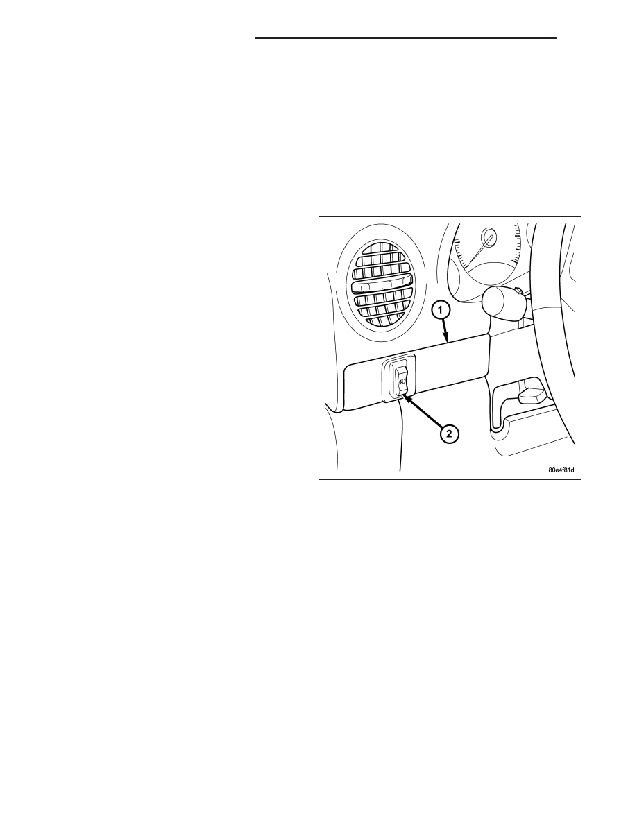
2. Remove the driver side outboard bezel (1) from the

instrument panel. (Refer to 23 - BODY/INSTRU-
MENT

PANEL/INSTRUMENT

PANEL

DRIVER

SIDE BEZEL - REMOVAL).

3. Disconnect the instrument panel wire harness con-

nector from the light bar lamp switch (2) connector
receptacle.

4. From the back of the trim bezel, depress the two

lower latch features on the switch housing and rock
the bottom of the switch out through the face of the
bezel.

5. From the back of the trim bezel, depress the two

upper latch features on the switch housing and
push the switch out through the face of the bezel.

INSTALLATION

WARNING: To avoid personal injury or death, on vehicles equipped with airbags, disable the supplemental
restraint system before attempting any steering wheel, steering column, airbag, occupant classification sys-
tem, seat belt tensioner, impact sensor, or instrument panel component diagnosis or service. Disconnect
and isolate the battery negative (ground) cable, then wait two minutes for the system capacitor to discharge
before performing further diagnosis or service. This is the only sure way to disable the supplemental
restraint system. Failure to take the proper precautions could result in accidental airbag deployment.

NOTE: A light bar lamp switch is used only on vehicles equipped with the optional light bar and auxiliary
off-road lamps.

8L - 94

LAMPS/LIGHTING - EXTERIOR

KJ

1. From the face of the driver side outboard bezel (1),

align the light bar lamp switch housing (2) to the
mounting hole in the bezel.

2. Push the switch into the mounting hole until it is

fully seated and each of the latch features is fully
engaged.

3. Reconnect the instrument panel wire harness con-

nector to the switch connector receptacle.

4. Reinstall the trim bezel and switch unit onto the

instrument panel. (Refer to 23 - BODY/INSTRU-
MENT

PANEL/INSTRUMENT

PANEL

DRIVER

SIDE BEZEL - INSTALLATION).

5. Reconnect the battery negative cable.

KJ

LAMPS/LIGHTING - EXTERIOR

8L - 95

MARKER LAMP

REMOVAL

BULB

NOTE: The following procedure applies only to vehicles manufactured for the North American market. Vehi-
cles manufactured for export markets do not have a bulb, socket or wiring provided to illuminate the front
side marker lamp. The front side marker lamp housing and lens are present, but serve only as a reflector on
export vehicles.

1. Turn the front wheels full lock toward the same

side of the vehicle as the lamp being serviced.

2. Disconnect and isolate the battery negative cable.

3. Remove the four fasteners securing the front of the

adjacent right or left front fender wheel liner to the
lower edge of the front bumper fascia (3) and the
outboard surface of the frame rail ahead of the
front wheel.

4. Reach between the front of the wheel liner and the

lower fascia to access the back of the front side
marker lamp unit housing (1).

5. Firmly grasp the front side marker bulb socket (2)

on the back of the lamp housing and rotate it coun-
terclockwise about 30 degrees to unlock it.

6. Pull the socket and bulb straight out from the

keyed opening in the housing.

7. Pull the base of the bulb straight out of the socket.

LAMP

NOTE: Vehicles manufactured for export markets do not have a bulb, socket or wiring provided to illuminate
the front side marker lamp. The front side marker lamp housing and lens are present, but serve only as a
reflector on export vehicles.

1. Turn the front wheels full lock toward the same

side of the vehicle as the lamp being serviced.

2. Disconnect and isolate the battery negative cable.

3. Remove the four fasteners securing the front of the

adjacent right or left front fender wheel liner to the
lower edge of the front bumper fascia and the out-
board surface of the frame rail ahead of the front
wheel.

4. Reach between the front of the wheel liner and the

lower fascia (3) to access the back of the front side
marker lamp unit housing (1).

5. If the vehicle is so equipped, firmly grasp the front

side marker bulb socket on the back of the lamp
housing and rotate it counterclockwise about 30
degrees to unlock it.

6. If the vehicle is so equipped, pull the socket and

bulb straight out from the keyed opening in the
housing.

8L - 96

LAMPS/LIGHTING - EXTERIOR

KJ

7. Slide the retaining clip (5) off of the pin (4) integral to the lower end of the lamp housing that secures the lamp

to the fascia.

8. Push the lower end of the lamp out through the outside of the fascia far enough to disengage the tab (2) at the

top of the lamp from the notch at the top of the lamp mounting hole.

9. Remove the lamp from the outside of the fascia.

INSTALLATION

BULB

NOTE: The following procedure applies only to vehicles manufactured for the North American market. Vehi-
cles manufactured for export markets do not have a bulb, socket or wiring provided to illuminate the front
side marker lamp. The front side marker lamp housing and lens are present, but serve only as a reflector on
export vehicles.

1. Align the base of the bulb with the front side

marker bulb socket (2).

2. Push the bulb straight into the socket until the base

is firmly seated.

3. Reach between the front of the adjacent right or

left front fender wheel liner and the lower bumper
fascia (3) to access the back of the lamp housing
(1).

4. Align the socket and bulb with the keyed opening

on the back of the housing.

5. Insert the socket and bulb into the housing until the

socket is firmly seated.

6. Rotate the socket clockwise about 30 degrees to

lock it into place.

7. Reinstall the four fasteners securing the front of the

wheel liner to the lower edge of the fascia and the
outboard surface of the frame rail ahead of the
front wheel.

8. Reconnect the battery negative cable.

LAMP

NOTE: Vehicles manufactured for export markets do not have a bulb, socket or wiring provided to illuminate
the front side marker lamp. The front side marker lamp housing and lens are present, but serve only as a
reflector on export vehicles.

KJ

LAMPS/LIGHTING - EXTERIOR

8L - 97


Content   ..  107  108  109  110   ..