Jeep Liberty KJ. Manual - part 1013


  Index      Jeep     Jeep Liberty KJ - service repair manual 2006 year


Search            


Content   ..  1011  1012  1013  1014   ..


Jeep Liberty KJ. Manual - part 1013


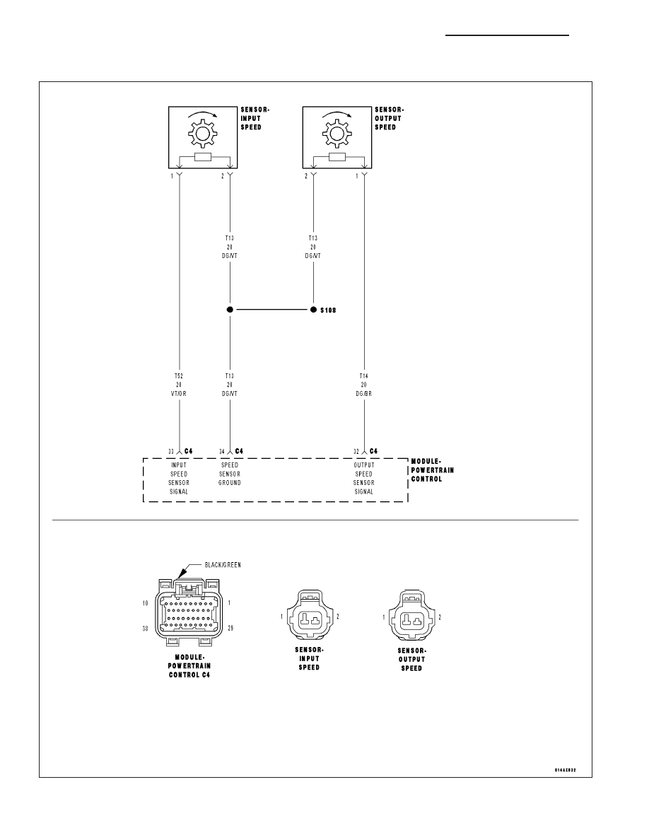
P0720-OUTPUT SPEED SENSOR CIRCUIT

For a complete wiring diagram Refer to Section 8W.

21 - 96

AUTOMATIC TRANSMISSION 42RLE - ELECTRICAL DIAGNOSTICS

KJ

When Monitored:
The transmission gear ratio is monitored continuously while the transmission is in gear.

Set Condition:
If there is an excessive change in the Output RPM in any gear.

Possible Causes

(T14) OUTPUT SPEED SENSOR SIGNAL CIRCUIT OPEN

(T13) SPEED SENSOR GROUND CIRCUIT OPEN

(T14) OUTPUT SPEED SENSOR SIGNAL CIRCUIT SHORT TO GROUND

(T14) OUTPUT SPEED SENSOR SIGNAL CIRCUIT SHORT TO VOLTAGE

(T13) SPEED SENSOR GROUND CIRCUIT SHORT TO VOLTAGE

OUTPUT SPEED SENSOR

POWERTRAIN CONTROL MODULE

Always perform the Pre-Diagnostic Troubleshooting procedure before proceeding. (Refer to 21 - TRANSMIS-
SION/TRANSAXLE/AUTOMATIC - 42RLE - STANDARD PROCEDURE)

Theory of Operation

The transmission system uses two speed sensors, one to measure input RPM and one to measure output RPM.
These inputs are essential for proper transmission operation. Therefore, the integrity of this data is verified through
system checks.

Diagnostic Test

1.

CHECK IF THE DTC IS CURRENT

Start the engine in park.

Raise the drive wheels off of the ground.

WARNING: Properly support the vehicle.
Firmly apply the brakes and place the transmission selector in drive.

WARNING: Be sure to keep hands and feet clear of rotating wheels.
Release the brakes and allow the drive wheels to spin freely.

NOTE: The drive wheels must be turning at this point.
With the scan tool, read the Output RPM

Is the Output RPM below 100?

Yes

>> Go To 2

No

>> Go To 8

2.

CHECK THE PCM AND WIRING USING THE TRANSMISSION SIMULATOR

Turn the ignition off to the lock position.

Remove the Starter Relay.

CAUTION: Removal of the Starter Relay will prevent the vehicle from being started in gear.

WARNING: The Starter Relay must be removed from the PDC. Failure to do so can result in personal injury
or death.

NOTE: Failure to remove the Starter Relay can cause a Transmission - No Response condition.
Install the Transmission Simulator, Miller tool #8333 and the Electronic Transmission Adapter kit.

Ignition on, engine not running.

With the Transmission Simulator, set the

9

Input/Output Speed

9

switch to

9

ON

9

and the rotary switch to the

9

3000/

1250

9

position.

KJ

AUTOMATIC TRANSMISSION 42RLE - ELECTRICAL DIAGNOSTICS

21 - 97

With the scan tool , read the Input and Output RPM.

Does the Input RPM read 3000 and the Output RPM read 1250 (within 50 RPM)?

Yes

>> Replace the Output Speed Sensor per the Service Information.

Perform 42RLE TRANSMISSION VERIFICATION TEST - VER 1. (Refer to 21 - TRANSMISSION/
TRANSAXLE/AUTOMATIC - 42RLE - STANDARD PROCEDURE)

No

>> Go To 3

3.

CHECK THE (T14) OUTPUT SPEED SENSOR SIGNAL CIRCUIT FOR AN OPEN

Turn the ignition off to the lock position.

Disconnect the PCM C4 harness connector.

Disconnect the Output Speed Sensor harness connector.

NOTE: Check connectors - Clean/repair as necessary.

CAUTION: Do not probe the PCM harness connectors. Probing the
PCM harness connectors will damage the PCM terminals resulting
in poor terminal to pin connection. Install Miller tool #8815 to per-
form diagnosis.
Measure the resistance of the (T14) Output Speed Sensor Signal circuit
between the Output Speed Sensor harness connector and the appropri-
ate terminal of Miller tool #8815.

Is the resistance above 5.0 ohms?

Yes

>> Repair the (T14) Output Speed Sensor Signal circuit for an

open.

Perform 42RLE TRANSMISSION VERIFICATION TEST -
VER 1. (Refer to 21 - TRANSMISSION/TRANSAXLE/AU-
TOMATIC - 42RLE - STANDARD PROCEDURE)

No

>> Go To 4

21 - 98

AUTOMATIC TRANSMISSION 42RLE - ELECTRICAL DIAGNOSTICS

KJ

4.

CHECK THE (T13) SPEED SENSOR GROUND CIRCUIT FOR AN OPEN

Measure the resistance of the Speed Sensor Ground circuit between
the appropriate terminal of Miller tool #8815 and the Output Speed Sen-
sor harness connector.

Is the resistance above 5.0 ohms?

Yes

>> Repair the (T13) Speed Sensor Ground circuit for an open.

Perform 42RLE TRANSMISSION VERIFICATION TEST -
VER 1. (Refer to 21 - TRANSMISSION/TRANSAXLE/AU-
TOMATIC - 42RLE - STANDARD PROCEDURE)

No

>> Go To 5

5.

CHECK THE (T14) OUTPUT SPEED SENSOR SIGNAL CIRCUIT FOR A SHORT TO GROUND

Measure the resistance between ground and the (T14) Output Speed
Sensor Signal circuit.

Is the resistance below 5.0 ohms?

Yes

>> Repair the (T14) Output Speed Sensor Signal circuit for a

short to ground.

Perform 42RLE TRANSMISSION VERIFICATION TEST -
VER 1. (Refer to 21 - TRANSMISSION/TRANSAXLE/AU-
TOMATIC - 42RLE - STANDARD PROCEDURE)

No

>> Go To 6

KJ

AUTOMATIC TRANSMISSION 42RLE - ELECTRICAL DIAGNOSTICS

21 - 99


Content   ..  1011  1012  1013  1014   ..