Jeep Liberty KJ. Manual - part 44
REMOVAL
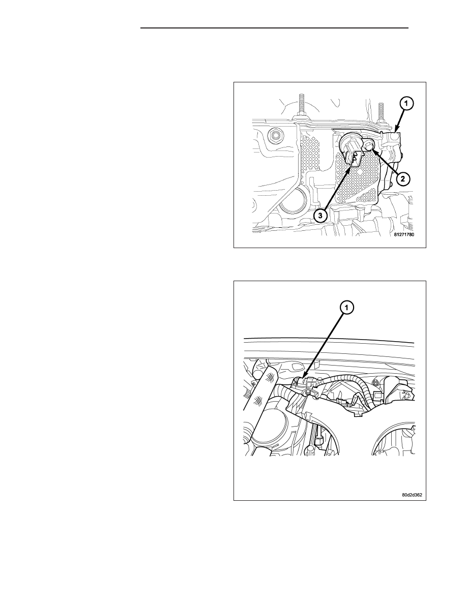
3.7L
The Camshaft Position Sensor (CMP) (3) is bolted to
the front/top of the right cylinder head (1).
1. Disconnect electrical connector at CMP sensor.
2. Remove sensor mounting bolt (2).
3. Carefully twist sensor from cylinder head.
4. Check condition of sensor O-ring.
2.8L TURBODIESEL
1. Disconnect negative battery cable.
2. Remove engine cover (Refer to 9 - ENGINE
COVER - REMOVAL).
3. Disconnect CMP sensor electrical connector.
4. Remove CMP sensor (1) retaining bolt and remove
sensor from cylinder head cover/intake manifold.
8I - 8
IGNITION CONTROL
KJ