Jeep Liberty KJ. Manual - part 28


  Index      Jeep     Jeep Liberty KJ - service repair manual 2006 year


Search            


Content   ..  26  27  28  29   ..


Jeep Liberty KJ. Manual - part 28


WARNING: If equipped with diesel engine, attempt to start engine a few times before proceeding with fol-
lowing step.

6. Rotate and hold ignition switch in Start position. Note cranking voltage and current (amperage) draw readings

shown on volt-ampere tester.

a. If voltage reads below 9.6 volts, refer to Starter Motor in Diagnosis and Testing. If starter motor is OK, refer

to Engine Diagnosis in 9, Engine for further testing of engine. If starter motor is not OK, replace faulty
starter motor.

b. If voltage reads above 9.6 volts and current (amperage) draw reads below specifications, refer to Feed Cir-

cuit Test in this section.

c. If voltage reads 12.5 volts or greater and starter motor does not turn, refer to Control Circuit Testing in this

section.

d. If voltage reads 12.5 volts or greater and starter motor turns very slowly, refer to Feed Circuit Test in this

section.

NOTE: A cold engine will increase starter current (amperage) draw reading, and reduce battery voltage read-
ing.

FEED CIRCUIT TEST

The starter feed circuit test (voltage drop method) will determine if there is excessive resistance in high-amperage
feed circuit. For complete starter wiring circuit diagrams, refer 8, Wiring Diagrams.

When performing these tests, it is important to remember that voltage drop is giving an indication of resistance
between two points at which voltmeter probes are attached.

Example: When testing resistance of positive battery cable, touch voltmeter leads to positive battery cable clamp
and cable connector at starter solenoid. If you probe positive battery terminal post and cable connector at starter
solenoid, you are reading combined voltage drop in positive battery cable clamp-to-terminal post connection and
positive battery cable.

The following operation will require a voltmeter accurate to 1/10 (0.10) volt. Before performing tests, be certain that
following procedures are accomplished:

Battery is fully-charged and load-tested. Refer to Battery in 8, Battery.

Fully engage parking brake.

If equipped with manual transmission, place gearshift selector lever in Neutral position and block clutch pedal
in fully depressed position. If equipped with automatic transmission, place gearshift selector lever in Park posi-
tion.

Verify that all lamps and accessories are turned off.

To prevent a gasoline engine from starting, remove Automatic ShutDown (ASD) relay. To prevent a diesel
engine from starting, remove Fuel Pump Relay. These relays are located in Power Distribution Center (PDC).
Refer to label on PDC cover for relay location.

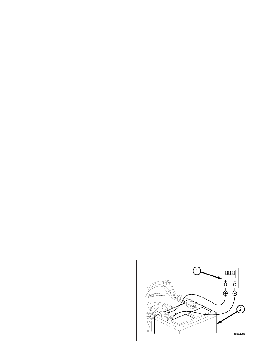
1. Connect positive lead of voltmeter (1) to negative

battery cable terminal post. Connect negative lead
of voltmeter to negative battery cable clamp.
Rotate and hold ignition switch in Start position.
Observe voltmeter (1). If voltage is detected, cor-
rect poor contact between cable clamp and termi-
nal post. Note: Certain diesel equipped models
use dual batteries. If equipped with dual battery
system, procedure must be performed twice,
once for each battery.

8F - 50

STARTING SYSTEM

KJ

2. Connect positive lead of voltmeter (1) to positive

battery terminal post. Connect negative lead of
voltmeter to battery positive cable clamp. Rotate
and hold ignition switch in Start position. Observe
voltmeter (1). If voltage is detected, correct poor
contact between cable clamp and terminal post.
Note: Certain diesel equipped models use dual
batteries. If equipped with dual battery system,
this procedure must be performed twice, once
for each battery.

3. Connect voltmeter (2) to measure between battery

positive terminal post and starter solenoid battery
terminal stud (3). Rotate and hold ignition switch in
Start position. Observe voltmeter. If reading is
above 0.2 volt, clean and tighten battery cable con-
nection at solenoid. Repeat test. If reading is still
above 0.2 volt, replace faulty positive battery cable.
Note: Certain diesel equipped models use dual
batteries. If equipped with dual battery system,
this procedure must be performed on driver
side battery only.

4. Connect voltmeter (1) to measure between nega-

tive battery terminal post and a good clean ground
on engine block (3). Rotate and hold ignition switch
in Start position. Observe voltmeter. If reading is
above 0.2 volt, clean and tighten negative battery
cable attachment on engine block. Repeat test. If
reading is still above 0.2 volt, replace faulty nega-
tive battery cable. Note: Certain diesel equipped
models use dual batteries. If equipped with dual
battery system, this procedure must be per-
formed twice, once for each battery.

KJ

STARTING SYSTEM

8F - 51

5. Connect positive lead of voltmeter (3) to starter

housing (1). Connect negative lead of voltmeter to
negative battery terminal post. Rotate and hold
ignition switch in Start position. Observe voltmeter.
If reading is above 0.2 volt, correct poor starter to
engine block ground contact. Note: Certain diesel
equipped

models

use

dual

batteries.

If

equipped with dual battery system, this proce-
dure must be performed on driver side battery
only.

6. If equipped with dual battery system (certain diesel

equipped models), connect positive lead of voltme-
ter to positive battery cable clamp on battery
located on left side of vehicle. Connect negative
lead of voltmeter to positive battery terminal post
on battery located on right side of vehicle. Rotate
and hold ignition switch in Start position. Observe
voltmeter. If reading is above 0.2 volt, clean and tighten battery cables at both batteries. Repeat test. If reading
is still above 0.2 volt, replace faulty positive battery cable.

If resistance tests detect no feed circuit problems, refer to Starter Motor in the Diagnosis and Testing.

CONTROL CIRCUIT TESTING

The starter control circuit components should be tested in the order in which they are listed, as follows:

Starter Relay - Refer to Starter Relay Diagnosis and Testing.

Starter Solenoid - Refer to Starter Motor Diagnosis and Testing.

Ignition Switch - Refer to Ignition Switch and Key Lock Cylinder

Clutch Pedal Position Switch - If equipped with manual transmission, refer to Clutch Pedal Position Switch
in 6, Clutch.

Park/Neutral Position Switch - If equipped with automatic transmission, refer to Park/Neutral Position
Switch 
in 21, Transmission.

Wire harnesses and connections - Refer to 8, Wiring Diagrams.

INSPECTION - STARTING SYSTEM

The following starting system components should be carefully inspected whenever any starting system problem is
encountered.

WARNING: On vehicles equipped with airbags, disable airbag system before attempting any steering wheel,
steering column, or instrument panel component diagnosis or service. Disconnect and isolate battery neg-
ative (ground) cable, then wait two minutes for airbag system capacitor to discharge before performing fur-
ther diagnosis or service. This is the only sure way to disable airbag system. Failure to take proper
precautions could result in accidental airbag deployment and possible personal injury.

Battery

Visually inspect battery for indications of physical damage and loose or corroded cable connections. Determine
state-of-charge and cranking capacity of battery. Charge or replace battery, if required. Refer to Battery for
battery cleaning and inspection procedures.

Ignition Switch

Visually inspect ignition switch for indications of physical damage and loose or corroded wire harness connec-
tions. Clean corroded connections as required. Refer to Wiring Diagrams. Refer to Ignition Switch and Key
Lock Cylinder 
for ignition switch service procedures.

8F - 52

STARTING SYSTEM

KJ

Clutch Pedal Position Switch

If vehicle is equipped with a manual transmission, visually inspect clutch pedal position switch for indications of
physical damage and loose or corroded wire harness connections. Clean corroded connections as required.
Refer to Clutch Hydraulic Linkage for clutch pedal position switch service procedures.

Park/Neutral Position Switch

If vehicle is equipped with an automatic transmission, visually inspect park/neutral position switch for indica-
tions of physical damage and loose or corroded wire harness connections. Clean corroded connections as
required. Refer to Park/Neutral Position Switch for park/neutral position switch service procedures.

Starter Relay

Visually inspect starter relay for indications of physical damage and loose or corroded wire harness connec-
tions. Clean corroded connections as required. Refer to Starter Relay for starter relay service procedures.

Starter Motor

Visually inspect starter motor for indications of physical damage and loose or corroded wire harness connec-
tions. Clean corroded connections as required. If problem being diagnosed involves improper starter engage-
ment, disengagement or noise complaints, starter motor should be removed. With starter motor removed,
inspect starter pinion and ring gears for damaged or missing teeth. Replace faulty components as required.
Refer to Starter Motor for removal/installation procedures.

Starter Solenoid

Visually inspect starter solenoid for indications of physical damage and loose or corroded wire harness con-
nections. Clean corroded connections as required. Refer to Starter Motor for starter solenoid service proce-
dures.

Wiring

Visually inspect starting system wire harnesses for indications of physical damage. Repair or replace any faulty
wiring, as required. Refer to Wiring Diagrams for repair or connector and terminal service procedures.

KJ

STARTING SYSTEM

8F - 53


Content   ..  26  27  28  29   ..