Jeep Grand Cherokee WK. Manual - part 968
P0406-EGR POSITION SENSOR CIRCUIT HIGH (CONTINUED)
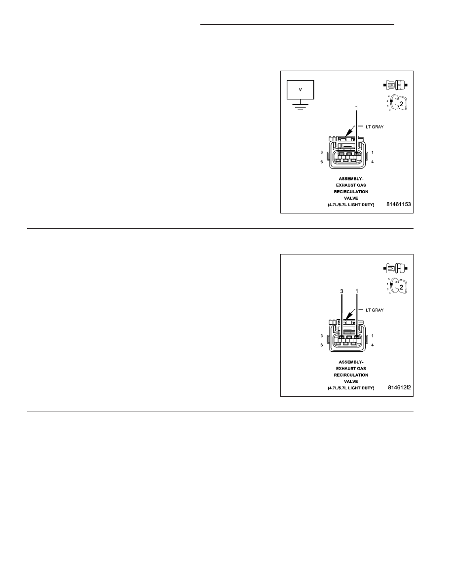
3.
(K34) EGR POSITION SENSOR SIGNAL CIRCUIT SHORTED TO BATTERY VOLTAGE
Ignition on, engine not running.
Measure the voltage on the (K34) EGR Sensor Signal circuit in the
EGR Solenoid harness connector.
Is the voltage above 0 volts?
Yes
>> Repair the short to battery voltage in the (K34) EGR Posi-
tion Sensor Signal circuit.
Perform the POWERTRAIN VERIFICATION TEST. (Refer
to 9 - ENGINE - STANDARD PROCEDURE)
No
>> Go To 4
4.
EGR SOLENOID ASSEMBLY
Turn the ignition off.
Connect the PCM harness connectors.
Connect a jumper wire between the (K34) EGR Position Sensor Signal
circuit and the (K900) Sensor ground circuit.
With the scan tool, monitor the EGR Position Sensor voltage.
Ignition on, engine not running.
Is the voltage below 0.5 of a volt?
Yes
>> Replace the EGR Solenoid Assembly.
Perform the POWERTRAIN VERIFICATION TEST. (Refer
to 9 - ENGINE - STANDARD PROCEDURE)
No
>> Go To 5
NOTE: Remove the jumper wire before continuing.
9 - 468
ENGINE ELECTRICAL DIAGNOSTICS
WK